INSTALLATION, OPERATION, &
MAINTENANCE MANUAL
TITLE: F7000 / 8000 Series Rev. T
Pilot-Operated Safety Relief Valve Page 25 of 43
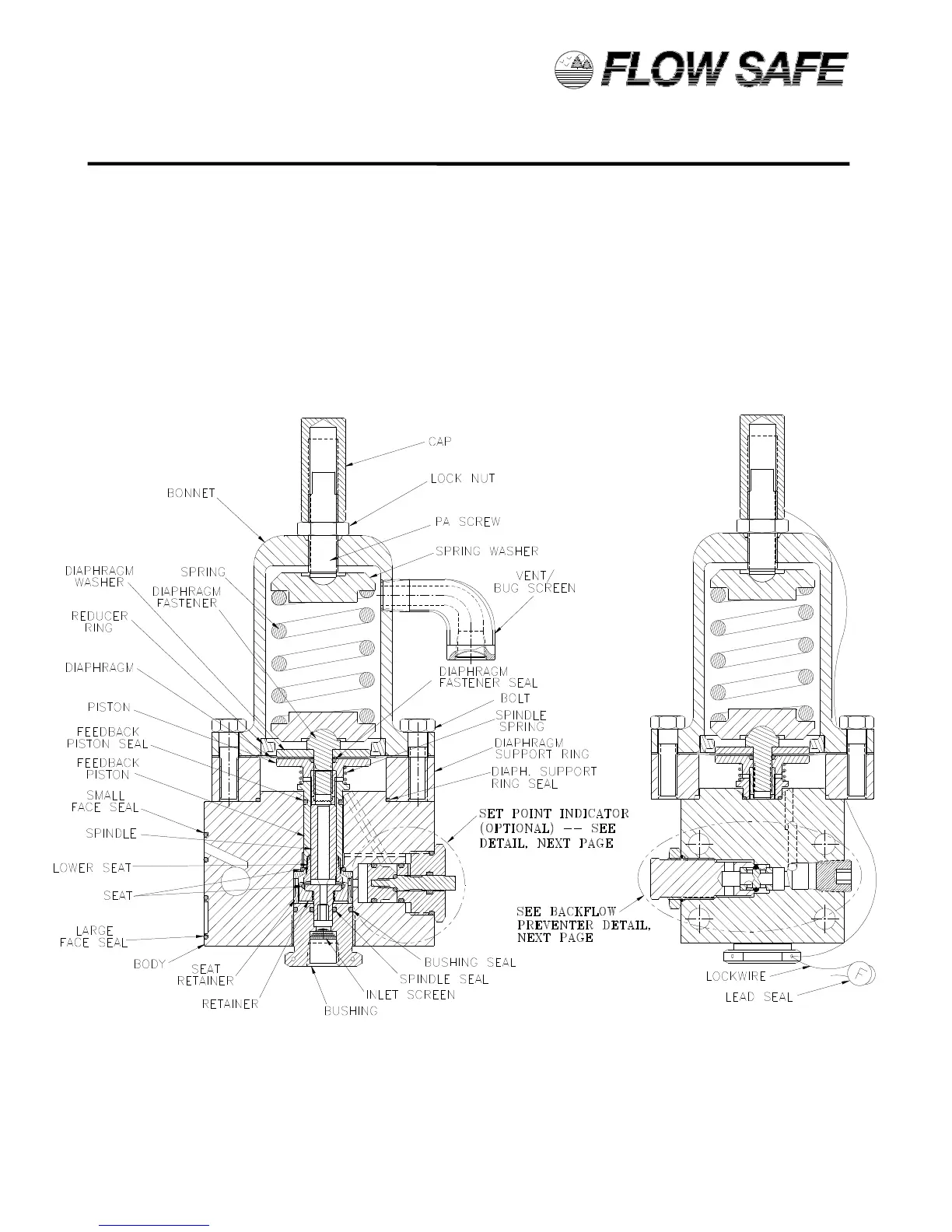
27) Install the vent / bug screen into the bonnet, ensuring that the male NPT end does not contact the
spring. Apply Teflon tape to threads before installing.
28) Assemble the PA screw and lock nut into the top of the bonnet.
29) Attach the cap to the PA screw, but do not tighten.
30) Install the face seals onto the external mounting face of the body.
31) The pilot valve is now completely assembled and ready to be set per Section 5.0.
32) If applicable, install lockwire and lead seal between PA screw cap, bonnet and inlet bushing.
Repair tag may be attached to wire.
F500 PILOT ASSEMBLY – LOW PRESSURE (15 – 285 psig)
 Loading...