FLEX User Instruction – 21TEM14546 EN
Page 12 of 43
3.3 Function in an RO system
The Flowserve FLEX™ is an isobaric energy recovery device designed for reverse osmosis (RO)
seawater desalination applications. It takes the energy of a high-pressure fluid waste stream
and transfers the pressure energy to a low-pressure fluid supply stream. The simple design does
not require any external power, has only one moving part, and uses corrosion-proof materials for
high reliability and long life.
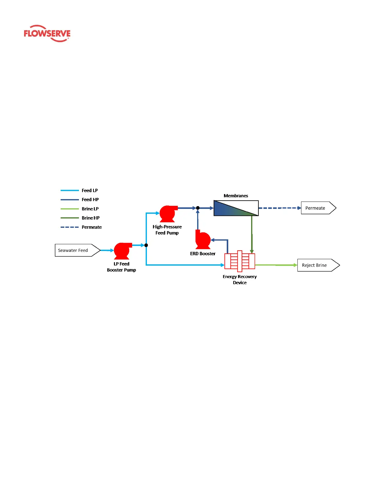
In an RO desalination application like the one shown in Figure 2, the high-pressure waste stream
entering the FLEX is brine leaving the membrane filters. The energy from this brine is transferred
to low-pressure seawater provided to the FLEX from the system’s low-pressure feed pump.
Seawater then leaves the FLEX at nearly the same pressure as the incoming brine. A small
booster pump is used to overcome piping friction losses between the brine outlet of the
membrane and the point that this seawater will be injected back into the membrane inlet. The
final outlet of the FLEX unit is the brine reject leaving at low-pressure. A control valve is used at
this location to maintain a minimum backpressure on the device.
Figure 2: Process flow diagram for a typical FLEX system
There are three sources of energy loss through the FLEX device: hydraulic, volumetric, and
mixing. Hydraulic loss occurs due to friction loss of fluid flowing through the device and
providing energy to drive rotation of the rotor. This is measured as a pressure differential from
inlet to outlet of the device on both the high-pressure and low-pressure sides. Volumetric loss is
caused by fluid leaking from high-pressure to low-pressure inside the device, providing
lubrication and cooling to the bearing surfaces. Mixing loss occurs due to turbulence at the
interface between brine and seawater inside the rotor ducts, and results in a small increase in
salinity of the seawater as it flows through the FLEX from low-pressure inlet to high-pressure outlet.
3.4 System design
A backpressure control valve must be included in the low-pressure brine discharge line. The
valve should be appropriately sized and selected to allow throttling of the flow to maintain
backpressure at or above the minimum level required by the FLEX. Maintaining backpressure at
or above the minimum required level will reduce cavitation and prolong life of FLEX unit(s).