FLEX User Instruction – 21TEM14546 EN
Page 13 of 43
Filtration of the process fluid must occur upstream of the FLEX device to avoid damaging the unit
and the precision clearances inside of it. Filters should have a maximum particle size of 20 μm
(0.8 mils) or smaller.
A circulation pump (or booster pump) is required on the high-pressure side of FLEX system piping.
This pump is used to overcome system resistance as process fluid flows from the membrane
outlet, through the FLEX, and back to the high-pressure feedwater inlet of the membranes. This
pump should be installed with either a variable speed drive or a throttling valve to control high
pressure flow rate through the FLEX.
Pressure relief devices should be provided on system piping to prevent over pressurization of
either the FLEX device or low-pressure system piping. Over pressurization may create a hazard
for personnel or result in damage to the FLEX device. It is recommended to install appropriately
sized and rated pressure relief devices on the high-pressure and low-pressure inlets to the FLEX.
Flushing lines should be connected to the system in a way that allow independent flushing of the
high-pressure and low-pressure system piping around the FLEX device.
Vent connections should be placed to ensure that system piping and FLEX units can be
completely flooded, and all air can be purged from the system before startup.
Isolation valves and drain lines should be appropriately placed in system piping to allow isolation
of the FLEX units(s) from the system for safe inspection and maintenance.
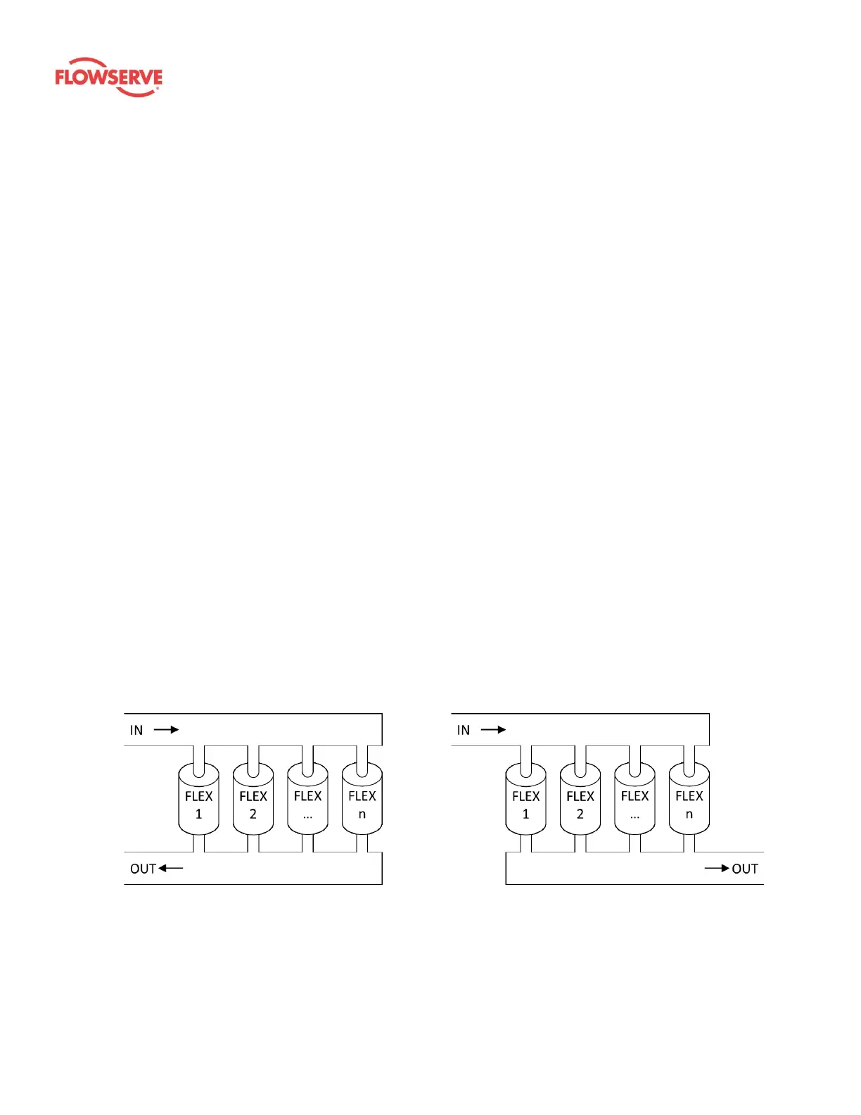
3.5 Header design
Headers can be used to place multiple FLEX units in parallel and achieve higher total system
flow than would be possible with any single unit. Care should be taken in designing the header
system to ensure that an even flow distribution between FLEX units is achieved. An uneven flow
distribution can result in excessive mixing and unreliable operation.
Two flow configurations can be used to design the headers for a rack of FLEX units: U-flow and Z-
flow configurations. U-flow has flow that enters and leaves on the same side of the rack. Z-flow
has flow that enters on one side of the rack and leaves on the other size. Examples of these
configurations are shown in Figure 3 and Figure 4.