FLEX User Instruction – 21TEM14546 EN
Page 14 of 43
An analysis of the total system resistance from header inlet to header outlet provides some
important guidelines on how to design headers to achieve an even flow distribution between
FLEX units operating in parallel with each other:
1. Maintaining low header flow velocity is more important than which configuration is
chosen. Lower header flow velocity will result in more even flow distribution between
FLEX units, but as a general guideline header flow velocity should be maintained below 3
m/s (10 ft/s).
2. A Z-flow configuration provides more even flow distribution between FLEX units than a U-
flow configuration.
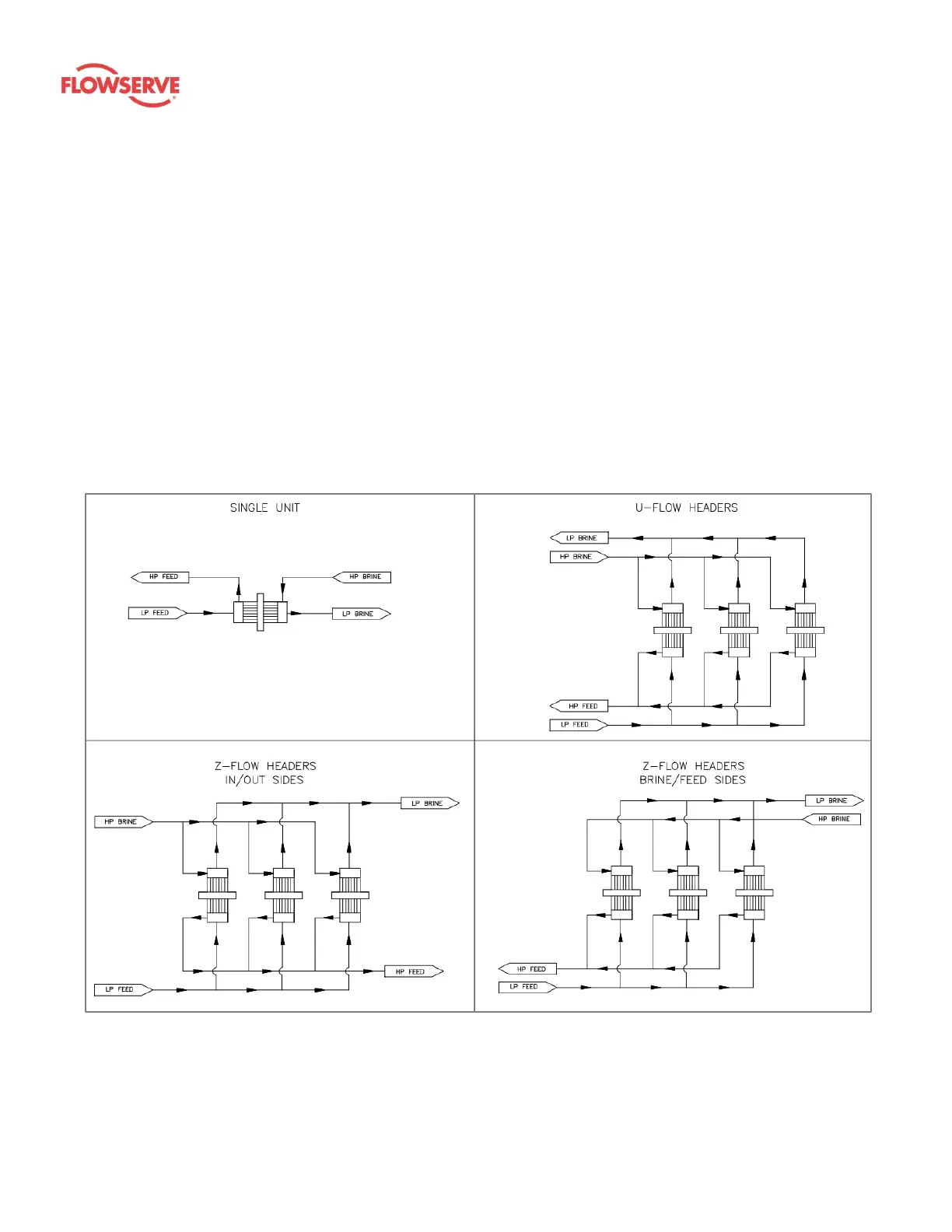
3. A Z-flow configuration can have high-pressure and low-pressure flow enter and exit on
either side of the rack and maintain the same flow distribution between units in the rack;
however, a U-flow header should have high-pressure and low-pressure flow enter and
exit on the same side of the rack so that any uneven flow distributions are equal on the
high-pressure and low-pressure sides, and the flow balance for each individual unit will
remain equal. Guidelines for acceptable header configurations are shown in Figure 5.
Figure 5: Acceptable header flow configurations
Mounting orientation is important for the design of mounting fixtures and system piping but does
not affect operation of the FLEX. FLEX units can be mounted in any orientation in the headers:
horizontal, vertical with brine on top, or vertical with brine on bottom.