IPS Detect
Page 19 of 35
OIM_FLS_IPS Detect_EN_14
Subject to technical changes! FLOWSERVE
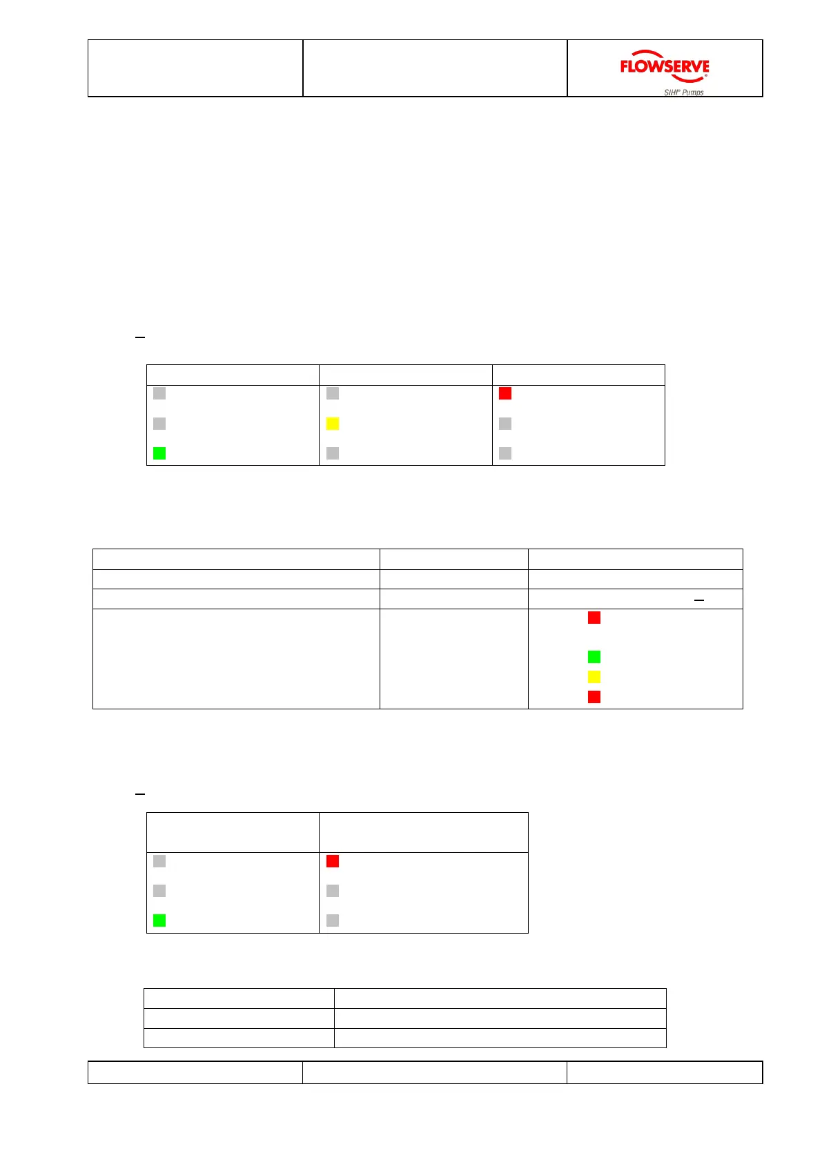
5.3 Monitoring operation
You can simply check the pump operation by taking a quick glance at the pump and
viewing the LED display.
Online detection is possible with a 4-20mA interface directly connected to conventional
control equipment.
5.3.1 Vibration velocity
LED Display
Normal operation Warning Failure
failure
warning
normal
failure
warning
normal
failure
warning
normal
4-20mA Interface
Measurement range Interface display
Calculation
Vibration velocity 0...10 mm/s 10...20 mA v
eff
[mm/s] = i[mA] - 10
Vibration velocity 0...20 mm/s 10...20 mA v
eff
[mm/s] = 2 * i[mA] 20
CM-mode
[CM = Condition Monitoring]
9,10,11 and
12 mA
9 mA (flashing)
CM-TRUE
10 mA normal
11 mA warning
12 mA failure
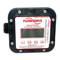
5.3.2 Condition monitoring
LED Display
Normal operation
( FALSE)
Condition monitoring
(TRUE)
failure
warning
normal
failure (flashing)
warning
normal
4-20mA Interface
Condition monitoring Interface display
FALSE Vibration velocity (see topic. 5.3.1)
TRUE 9 mA