IPS Detect
Page 9 of 35
OIM_FLS_IPS Detect_EN_14
Subject to technical changes! FLOWSERVE
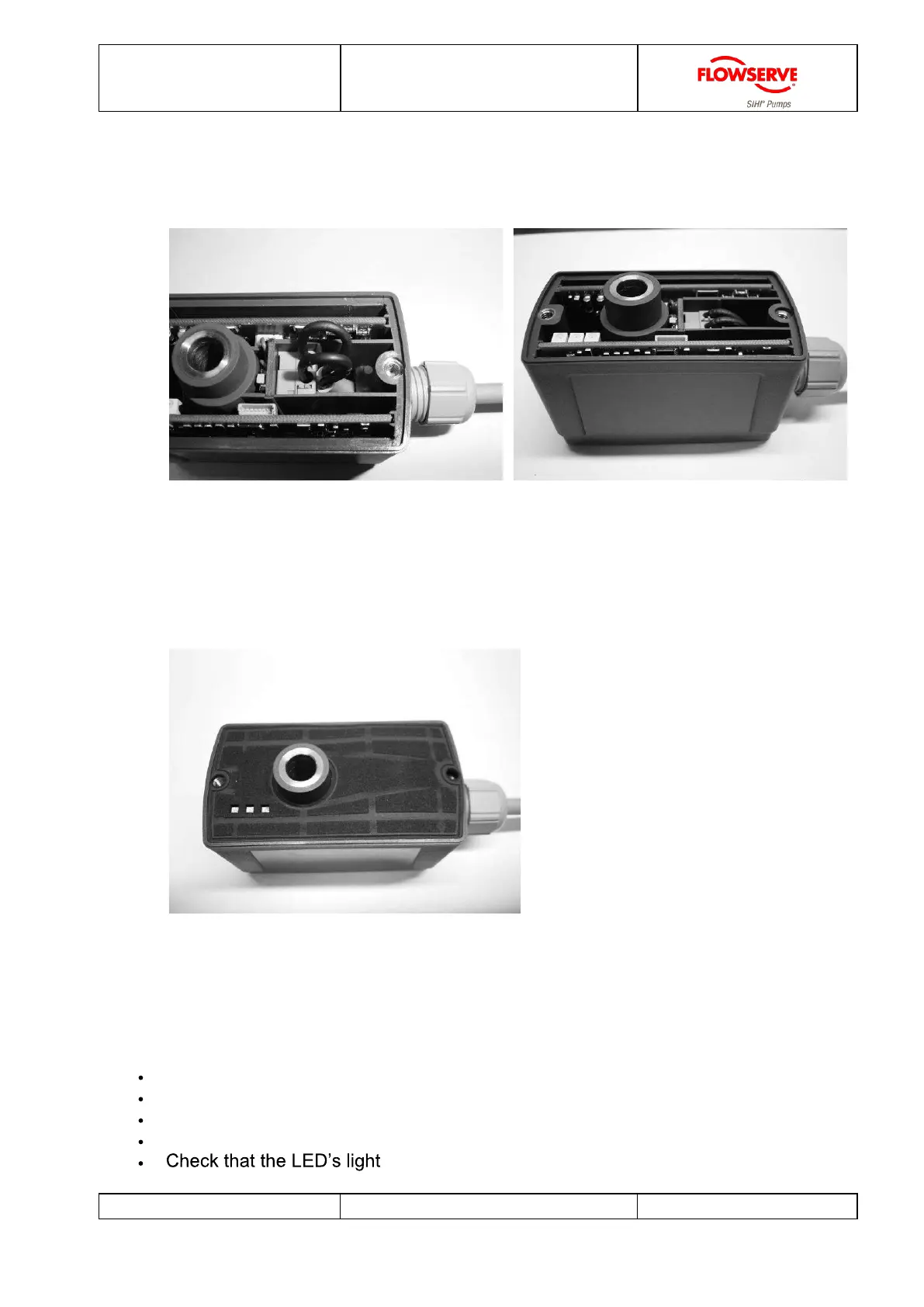
5. Pull back the cable in order to remove any excess from within the terminal head.
Subsequently tighten the cable gland.
Picture: Connected cable Picture: Cable inside of the housing
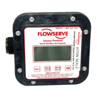
6. Replace the gasket ensuring that it does not cover the LEDs and then tighten with
the two screws.
Picture: Sensor gasket
4.2 Electrical connection check
Perform the following checks after completing electrical installation of the device.
Is the connection in accordance with the description?
Is the cable gland firmly tightened?
Is the fitting of the gasket correct and the LEDs clearly visible?
Are the housing cover screws tightened correctly?
-up once the electrical supply is (re) connected.