11
Limitorque B320 Series FCD LMENIM3201-02 – 01/15
flowserve.com
4.2 Safety Practices
The following check points should be performed to maintain safe operation of the B320 gear
operator:
• Set up a periodic operating schedule on infrequently used valves.
• Ensure that the limit and/or torque switches on any electric actuator fitted to the bevel gear
operator are correctly and appropriately adjusted.
4.3 Installation
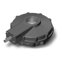
The B320 series of gear operators has been designed to transmit torque as well as thrust. The gear
operator can be supplied with a threaded stem nut, keyed stem nut, or a blank stem nut.
4.3.1 Installing an Operator with a Threaded Stem Nut
1. Position operator above the valve stem.
2. Rotate the operator handwheel or wrench nut several turns until there is positive engagement
between the valve stem and the operator stem nut.
3. Rotate the handwheel to lower the operator onto the valve until contact has been made with the
valve flange.
4. Bolt the gear operator securely to the valve mounting flange.
4.3.2 Installing an Operator with a Blank Stem Nut
(B320-10 through -90, one-piece)
1. Remove the thrust ring from the base of the operator.
a CAUTION: Care must be taken to ensure that the O-ring seals located on the ring are not
damaged.
2. Remove the stem nut assembly consisting of a bronze nut and two needle roller bearings with
washers.
3. Remove bearings and washers. Place them in a clean and dry area until reassembly.
4. Machine the stem nut to suit the valve stem.
a CAUTION: Care should be taken to ensure that the clamping devices used during machining do
not damage surfaces of the stem nut.
5. Reassemble the operator, reversing steps 1, 2, and 3.
a. Install bearings and washers onto the bronze stem nut.
b. Install the assembly into the thrust base.
c. Bolt the thrust base assembly to the main housing.
a CAUTION: Ensure that no dirt or foreign material enters the operator.