23
Limitorque B320 Series FCD LMENIM3201-02 – 01/15
flowserve.com
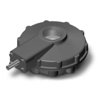
Table 6.4 – 3:1 SGA Parts List for B320-10 through -40
Piece Quantity Description
26A 1 Key
27 4 Lockwasher
28 4 Hex Head Cap Screw
29 1 Snap Ring
30 1 Spur Gear Housing
31 1 Spur Gear Cover
32 5 Bushing
33 2 Dowel Pin
34 4 Hex Head Cap Screw
35 4 Lockwasher
36 2 Expansion Plug
37 1 Input Shaft and Pinion
38 1 Idler Gear
39 1 Key
40 1 Output Gear
46 1 O-ring
6.3.3 Disassembly of 6.3:1, 10.3:1, and 10.8:1 Spur Gear
Attachments for B320-50, -70, and -80
(Piece numbers refer to Figure 6.7 and Table 6.5).
1. Remove the Hex Head Cap Screws (piece #47) and Lockwashers (piece #35).
2. Remove the End Cover (piece #44) and O-ring (piece #46), followed by the Input Shaft and Pinion
(piece #37) and outer Ball Bearing (piece #45).
3. Remove the Hex Head Cap Screw (piece #34) and Lockwasher (piece #35).
4. Remove the Spur Gear Cover (piece #31), followed by the Idler Shaft subassembly (piece #48),
inner Ball Bearing (piece #45), and Final Gear (piece #40).
5. Remove the Socket Head Cap Screws (piece #53) and Lockwashers (piece #54).
6. Remove the Spur Gear Housing (piece #30).
7. Continue disassembly as detailed in Section 6.1, Disassembly and Reassembly of B320-10 through -80.
6.3.4 Reassembly of 6.3:1, 10.3:1, and 10.8:1 Spur Gear
Attachments for B320-50, -70, and -80
(Piece numbers refer to Figure 6.7 and Table 6.5).
1. Install the Spur Gear Housing (piece #30), using the Socket Head Cap Screws (piece #53) and
Lockwashers (piece #54).
2. Install the Final Gear (piece #40), inner Ball Bearings (piece #45), Idler Shaft subassembly (piece
#48), and the Spur Gear Cover (piece #31).
3. Install the Spur Gear Cover (piece #31), using the Hex Head Cap Screws (piece #34) and
Lockwashers (piece #35).
4. Install the outer Ball Bearing (piece #45) and Input Shaft and Pinion (piece #37).
5. Install the O-ring (piece #46) and End Cover (piece #44), using the Hex Head Cap Screws (piece
#47) and Lockwashers (piece #35).