21
Limitorque B320 Series FCD LMENIM3201-02 – 01/15
flowserve.com
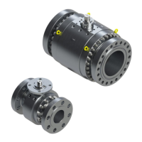
Table 6.3 – B320-90 Parts List
Piece Quantity Description
91 1 Bevel Housing
93 1 Torque Drive Sleeve
94 1 Bevel Cap
95 1 Input Shaft/Pinion
96 1 Bevel Gear
97 1 Threaded Collar
99 1 Quad Ring
100 1 O-ring
102 66 Ball Bearing
103 2 Roller Bearing Cone
104 2 Roller Bearing Cup
105 2 Spacer-Pinion
106 1 Spacer-Input Bearing
107 6 Hex Head Cap Screw
108 6 Lockwasher
109 12 Soc Head Cap Screw
110 12 Lockwasher
111 6 Hex Head Cap Screw
113 6 Lockwasher
114 1 Thrust Housing
115 2 Roller Bearing Cone
116 2 Roller Bearing Cup
117 1 Thrust Drive Sleeve (2-pc)
118 1 Thrust Plate
119 8 Hex Head Cap Screw
120 1 Quad Ring
121 1 Bushing
122 1 Quad Ring
336 1 Grease Fitting
347 1 Pipe Plug
392 1 Stem Nut
393 1 Key
394 1 Thrust Drive Sleeve (1-pc)
395 1 Lockwasher
6.3 Disassembly and Reassembly of Spur Gear
Attachments
6.3.1 Disassembly of 3:1 Spur Gear Attachment for B320-10
through -40
(Piece numbers refer to Figure 6.6 and Table 6.4).
1. Remove Hex Head Cap Screws(piece #34) and Lockwashers (piece #35).
2. Remove the Spur Gear Cover (piece #31) and O-ring (piece #46), followed by the Input Shaft and
Pinion (piece #37), Idler Gear (piece #38), and Output Gear (piece #40).