Limitorque B320 Series FCD LMENIM3201-02 – 01/15
4
Figures
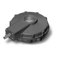
Figure 2.1 – B320 Bevel Gear Operator 7
Figure 2.2 – B320 Nameplate 8
Figure 6.1 – B320-10 and 20 Parts Diagram 17
Figure 6.2 – B320-30 and -40 Parts Diagram 17
Figure 6.3 – B320-50 and -70 Parts Diagram 18
Figure 6.4 – B320-80 Parts Diagram 18
Figure 6.5 – B320-90 Parts Diagram 20
Figure 6.6 – 3:1 SGA Parts Diagram for B320-10 through -40 22
Figure 6.7 – 6.3:1, 10.3:1, and 10.8:1 SGA Parts Diagram for B320-50 through 80 24
Figure 6.8 – 5:1 SGA Parts Diagram for B320-90 26
Figure 6.9 – 17.5:1 SGA Parts Diagram for B320-90 28
Tables
Table 3.1 – Operator Weights 9
Table 5.1 – Lubricant Quantities 14
Table 6.1 – Quantity of Ball Bearings 15
Table 6.2– Common Parts List 19
Table 6.3 – B320-90 Parts List 21
Table 6.4 – 3:1 SGA Parts List for B320-10 through -40 23
Table 6.5 – 6.3:1 , 10.3:1, and 10.8:1 SGA Parts List for B320-50 through 80 24
Table 6.6 – 5:1 SGA Parts List for B320-90 26
Table 6.7 – 17.5:1 SGA Parts List for B320-90 29