Limitorque MX Maintenance and Spare Parts FCD LMENIM2314-00 – 07/08
146
STEP 3
Route the terminal block plug bundle over the top of the reverser assembly and mount the terminal
block per Section 5.8.2, Steps 7 through 10.
STEP 4
Mount the solid state reverser assembly (1-52) in the unit housing using the existing M4 contactor
mounting screws (8-28).
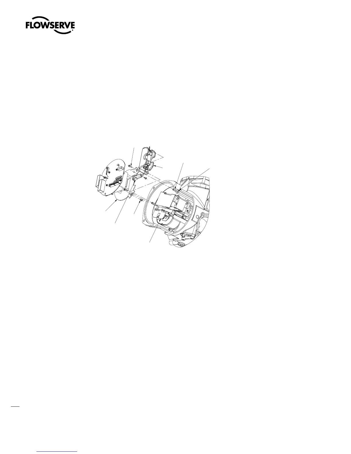
Figure 5.24 – Control module reinstallation
1-53
1-19
1-57
FUSE
BLOCK PLUG
1-45
1-55
1-56
1-54
STEP 5
Mount the washer (1-56) and the third standoff (1-55) in the housing.
STEP 6
Mount the motor per Section 4.1.2.
STEP 7
Mount the Main/LCS, and if applicable, an optional board into CP using M4 Screws (7-44) per
Section 5.2.2.
NOTE: Only one optional board may be used with the SSMR, either I/O or Network (but not both) in
the same actuator.
STEP 8
Mount the SSMR fuse assembly (1-53) using two pan head machine screws (1-57). See Figure 5.23.
Swanson Flo | 800-288-7926 | www.swansonflo.com