1 of 5
Piezo Replacement Instructions
These instructions describe the procedure for exchanging standard temperature (-4ºF to
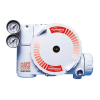
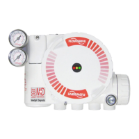
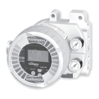
176ºF/-20ºC to 80ºC) piezo module assemblies on the Flowserve Logix 3200IQ positioner
with low temperature (-40ºF to 176ºF/-40ºC to 80ºC) assemblies. These instructions
supplement the 3200IQ Installation, Operating, and Maintenance (IOM) Instructions (FCD
LGAIM0058-00).
1. Remove main housing cover and driver
module cover by unscrewing the covers.
WARNING: To prevent ignition of
hazardous atmospheres, disconnect supply
circuit before opening. Keep assembly
tightly closed when in operation.
2. Remove the plastic main control board (PCB)
cover by removing two (2) short cover screws,
and one (1) long cover screw.
3. Unplug the red and black 2-wire piezo connector.
HOUSING
COVER
MODULE
COVER



 Loading...