13.6 Replacing the Electronics
Refer to Figure 26: Piezo Installation and Figure 27:
Replacing the Electronics.
Removal:
1 Make sure the valve is bypassed or in a safe condition.
2 Disconnect power to the positioner.
3 Remove the inner cover by removing the two PCB
cover retaining screws.
4 Unscrew the five electronics module retaining screws.
5 Gently remove the electronics by holding the terminal
block and lifting the electronics from the housing.
Installation:
1 Verify that the 4 pressure sensor O-rings are in the
electronics assembly.
2 Verify that the piezo O-rings are placed in the Housing.
3 Verify that the piezo is plugged into the bottom of the
electronics assembly.
4 Place the electronics assembly into the housing,
aligning the pressure sensor O-rings with the four holes
in the housing.
5 Tighten the 5 electronics assembly screws down, in a
star-shaped pattern, to verify even pressure.
6 Torque screws to 0.9 N-m (8 in-lb).
7 Place inner cover over electronics assembly and
tighten screws in a back and forth pattern to verify even
pressure.
8 Torque screws to 0.9 N-m (8 in-lb).
9 Reconnect the valve, mounting, and power as directed
by this manual.
10 Recalibrate as directed by this manual.
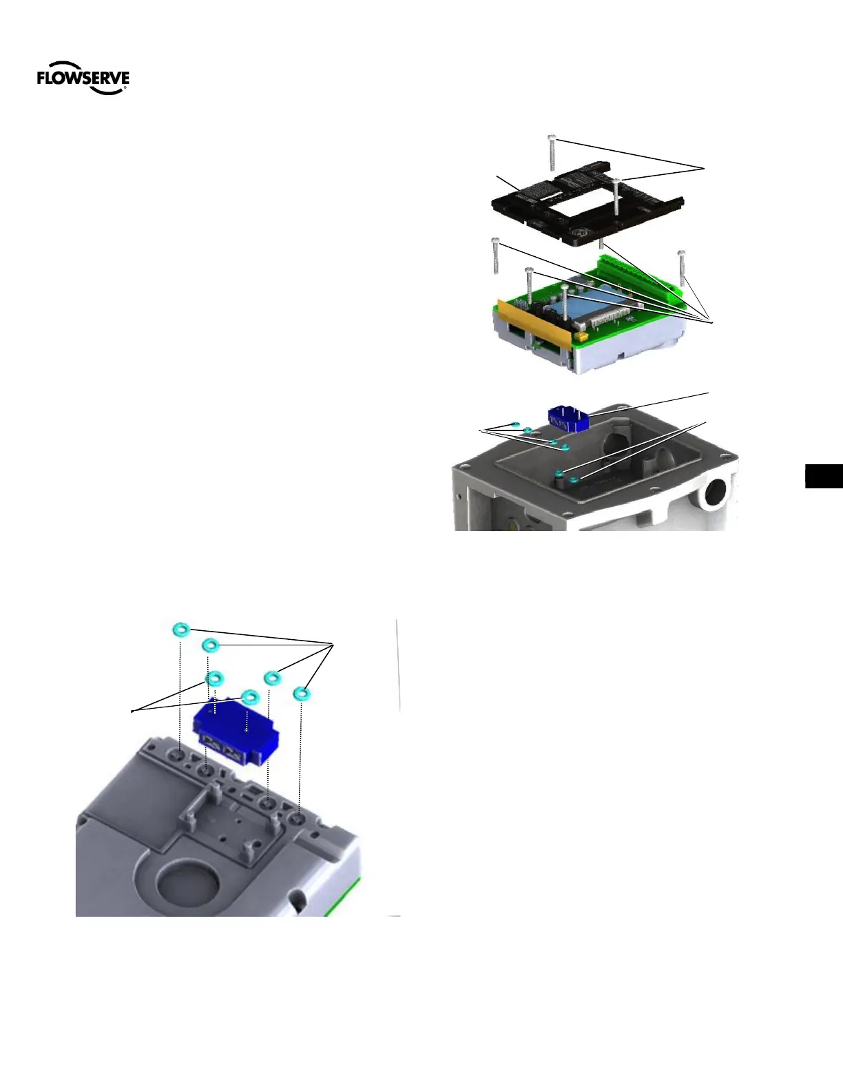
Figure 26: Piezo Installation
Figure 27: Replacing the Electronics
13.7
13.8 Replacing the Shaft Assembly
Refer to Figure 28: Replacing the Shaft Assembly
Removal:
1. Make sure the valve is bypassed or in a safe condition.
2. Disconnect power and conduit to the positioner.
3. Unmount the positioner from actuator and disengage the
shaft assembly from the follower arm assembly.
4. Place the positioner facedown so that the shaft is pointing
up and use a Phillips Screwdriver #2 to remove the three
feedback screws.
5. Discard the shaft assembly and screws.
Installation:
1. Apply 3M Scotch-Weld Threadlocker TL22 or Loctite 243
to the three holes on the back of the positioner housing.
2. Insert and align the new shaft assembly with the back of
the housing.
3. Using a Phillips Screwdriver #2, torque the three screws
to 0.9 N-m (8 in-lb).
4. Adjust the positioner to the correct mounting orientation.
Connect the shaft assembly to the follower arm assembly
within the working range of the shaft assembly. Finish
mounting the positioner.
5. Reconnect power as directed by this manual.
6. Perform a Stroke Calibration as directed by this manual.
 Loading...
