9.3 Additional Hot Key Calibrations
Hot keys can be used to initiate other function and component
calibrations, such as a command input calibration, an analog
input calibration, an analog output calibration and a feedback
calibration. Refer to APPENDIX F – HOT KEYS for information
about initiating these calibrations.
9.4 Tuning Options
Use the Selectable GAIN Switch to adjust the gain at any time
during operation. This adjustment takes effect immediately.
For faster response select settings above “E” (F-J). For a
more stable response, select settings below “E” (B-D). See
Figure 23: Selectable Gain Switch.
Quick-Cal Custom Gains – This is typically the fastest way to
achieve ideal gains. Set the Auto-Tune Configuration Switch
to “On” and the Selectable GAIN Switch to “E.” Then perform
a Quick-Cal. During the Quick-Cal, custom tuning parameters
will be determined based on measured response parameters.
Fine tune the gains by adjusting the Selectable GAIN Switch.
Selecting “D” “C” or “B” will progressively provide a more
stable response. Selecting “F” through “J” will progressively
provide a more active response. In most cases selecting “E”
will give the best results and is the default setting for all
actuator sizes. Raising or lowering the Selectable Gain Switch
setting is a function of the positioner/valve response to the
control signal, and is not actuator size dependent.
Standard Preset Gains – If standard, preset gains are desired,
set the Auto-Tune Configuration Switch to Off. After
performing a Quick-Cal, use the Selectable GAIN switch to the
desired level (“B” – “J”). The standard, preset gain settings are
not affected by Quick-Cal.
It may be necessary to set the gain switch BEFORE the Quick
Cal. Very fast stroking valves may need to be at lower gains
and very slow stroking valves may need to be at higher gains.
Custom Manual Gains – To set gains manually, set the
selectable GAIN switch to “A.” Changing the switch from “B” to
“A” will write the standard “B” settings into the “A” parameters,
allowing a starting point for modification. Similarly, changing
the switch from “J” to “A” will write the standard “J” settings into
the “A” parameters. Custom tuning values can then be entered
using the Display Menu, a Handheld or ValveSight DTM. With
the Selectable GAIN Switch set to “A,” the tuning will not be
modified during a Quick-Cal.
9.5 Factory Reset
To perform a factory reset, hold the QUICK-CAL button
while applying power. Factory reset causes a reset of all the
internal variables to factory defaults, including calibration. The
positioner must be re-calibrated after a factory reset. Restore
tag names and other user configured limits, alarm settings,
and valve information.
NOTE: For HART position, a factory reset will always reset
the command source to analog 4-20 mA.
CAUTION: Performing a factory reset may result in the
inability to operate the valve until properly reconfigured. Notify
proper personnel that the valve may stroke, and make sure the
valve is properly isolated.
10 OPERATION – USER
INTERFACE
10.1 LCD
The optional LCD provides a variety of useful information and
functions. The Main View shows important information using
icons and scrolling status lines. See Figure 25 for more detail.
Use the directional buttons to navigate from the
Main View to the LCD menu. This menu provides detailed
information and allows the user to perform common functions.
NOTE: The LCD backlight may change brightness during
use and is normal. The backlight uses any residual power not
used by other functions of the circuitry. When current supply
is low (4mA) the screen will appear darker. When current
supply is high (20mA) the screen will appear brighter. Also
note, the LCD may not be readable at temperatures below
-20°C (-4°F) and temperatures above 70°C (158°F).
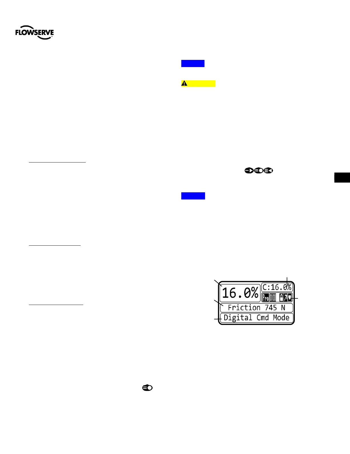
The main view provides an instant display of important status
parameters: Position, Final Command, Scrolling Status
Message, Current Alarm Status and Status Icons.
Figure 24: Display Main View
10.1.1 Position and Final Command
Shown always are the current Position and Final Command.
The Final Command is the command adjusted according to a
Characterization Curve, Tight Shut Off, or Soft Limits that have
been applied. Final Command should match the Position.
10.1.2 Scrolling Status Messages
 Loading...
