SVCN 7 INSTALLATION, OPERATION, & MAINTENANCE
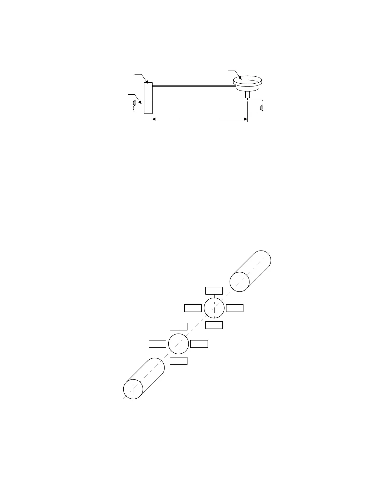
6. Securely attach the bracket to a length of rigid pipe, and install the indicator at the distance
determined in step 5 above. (see
Figure 2-9).
Pipe
Bracket
Dial Indicator
Bracket Span
Figure 2-9 Determining Bar Sag
7. Hold the pipe with the indicator facing up and set at "0". Without touching bracket, rotate the
pipe 180° so that the indicator is facing down. Read the indicator and record the reading. This
is the amount of bar sag.
8. Rotate the pipe again so that indicator is facing up. It must return to "0".
9. Repeat steps 7 and 8 to confirm reading.
NOTE
All indicator readings must be taken on the periphery or rim
of the coupling hub or shaft, or on the opposite bracket.
They must be recorded as viewed from the fixed unit (pump).
(see
Figure 2-10).
FIXED UNIT
3
12
3
6
9
1
2
4
3
12
3
6
9
1
2
4
MOVABLE UNIT
Figure 2-10 Alignment Orientation
10. Attach one bracket to the driver coupling hub or shaft, and the other to the pump hub or shaft.
Each indicator will read on the opposite bracket, coupling hub, or shaft. (see
Figure 2-8)
DO2604-13 - 2-10 -