HF110PEN_v0501_04
Page 18
6 - ANALOG OUTPUT (CONTINUED)
FILTER
67
This function is used to stabilize the analog output signal.
The output value is updated every 0.1 second. With the help of this digital
filter a more stable but less precise reading can be obtained.
The filter principal is based on three input values: the filter level (01-99),
the last analog output value and the last average value. The higher the
filter level, the longer the response time on a value change will be.
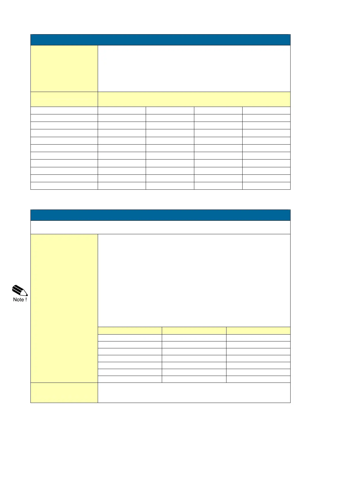
Below, several filter levels with their response times are indicated:
FILTER VALUE RESPONSE TIME ON STEP CHANGE OF ANALOG VALUE.
TIME IN SECONDS
50% INFLUENCE 75% INFLUENCE 90% INFLUENCE 99% INFLUENCE
01 filter disabled filter disabled filter disabled filter disabled
02 0.1 second 0.2 second 0.4 second 0.7 second
03 0.2 second 0.4 second 0.6 second 1.2 seconds
05 0.4 second 0.7 second 1.1 seconds 2.1 seconds
10 0.7 second 1.4 seconds 2.2 seconds 4.4 seconds
20 1.4 seconds 2.8 seconds 4.5 seconds 9.0 seconds
30 2.1 seconds 4 seconds 7 seconds 14 seconds
50 3.5 seconds 7 seconds 11 seconds 23 seconds
75 5.2 seconds 10 seconds 17 seconds 34 seconds
99 6.9 seconds 14 seconds 23 seconds 45 seconds
7 - RELAY OUTPUT
One transistor or mechanic relay output is available as scaled pulse output according to the
accumulated total.
PERIOD TIME
PULSE OUTPUT
71
The period time determines the time that the transistor or relay will be
switched; in other words the pulse length. The minimum time between the
pulses is as long as the selected period time.
One period is approx. 7.8 msec. If the value selected is “zero”, the pulse
output is disabled. The maximum value is 255 periods.
Note: If the frequency should go out of range - when the flowrate
increases for example - an internal buffer will be used to "store the missed
pulses": As soon as the flowrate reduces again, the buffer will be
"emptied".
It might be that pulses will be missed due to a buffer-overflow, so it is
advised to program this setting within it's range.
If a mechanic relay is used for the pulse output, it is recommended to
reduce the max. output frequency to 0.5Hz, else the life time will be
reduced significantly.
NUMBER OF PERIODS PERIOD TIME MAX. FREQUENCY
0 disabled disabled
1 0,0078 seconds 64 Hz.
2 0,0156 seconds 32 Hz.
3 0,0234 seconds 21 Hz.
64 0,5000 seconds 1 Hz.
255 1,9922 seconds 0.25 Hz.
PULSE PER
72
According to the measurement unit settings for total, a pulse will be
generated every X-quantity. Enter this quantity here while taking the
displayed decimal position and measuring unit into account.