HF110PEN_v0501_04
Page 30
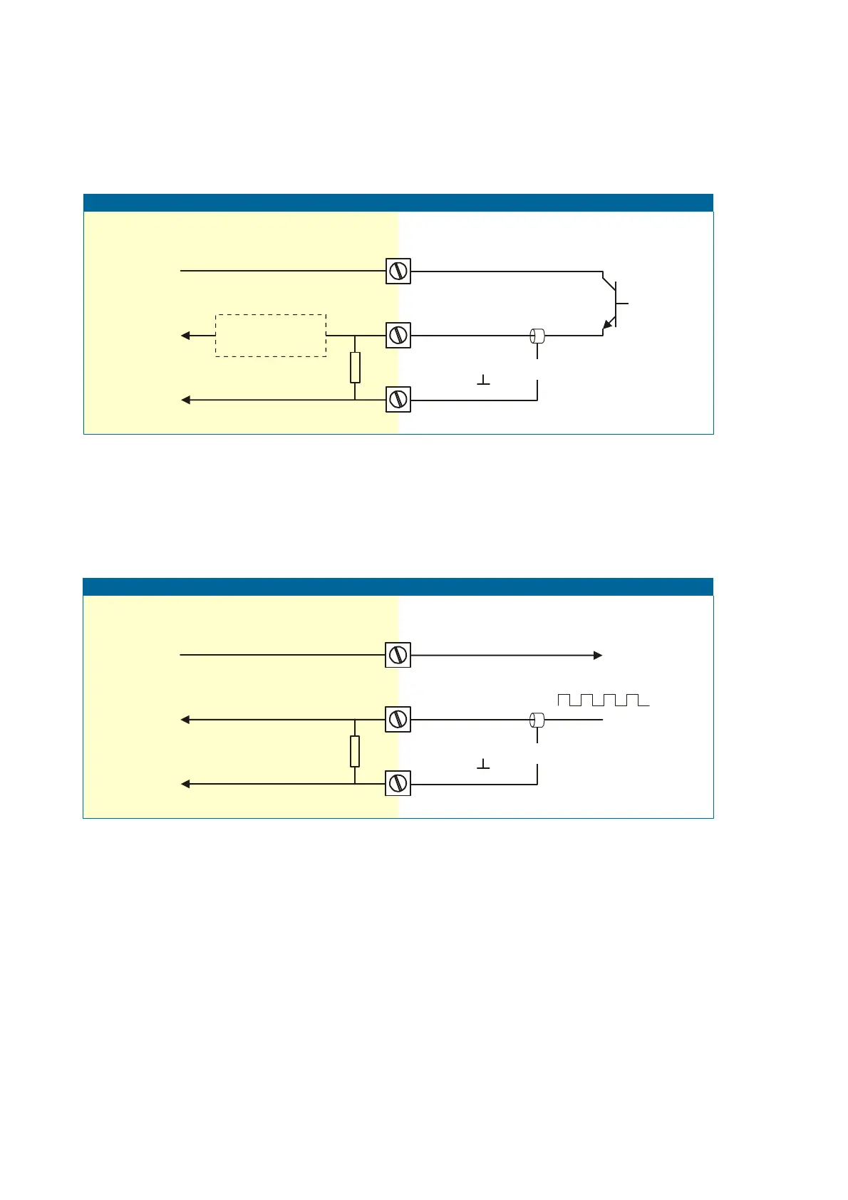
Pulse-signal PNP / PNP-LP:
The F110-P is suitable for use with flowmeters which have a PNP output signal. 3.2V is offered on
terminal 11 which has to be switched by the sensor to terminal 10 (SIGNAL). For a reliable pulse
detection, the pulse amplitude has to go above 1.2V. Signal setting PNP-LP employs a low-pass
signal noise filter, which limits the maximum input frequency - read par. 3.2.3.
A sensor supply voltage of 8.1, 12 or 24V DC can be provided with power supply type PD, PF, PM.
For a signal detection level of 50% of the supply voltage: please refer to "active signals".
Active signals 8.1V - 12V and 24V:
If a sensor gives an active signal, please read par. 3.2.3. The detection levels are 50% of the
selected supply voltage; approximately 4V (ACT_8.1) or 6V (ACT_12) or 12V (ACT_24).
Active signal selection may well be desired in the case of power supply type PD, PF, PM being
supplied for sensor supply.
INTERNAL EXTERNAL
Active signal input
10
Common ground unit
SIGNAL
9
GND
shielding
11
+3.2V DC (type PD, PF, PM: 8.1V, 12V, 24V)
Resistance value:
see signal selection
INTERNAL EXTERNAL
PNP signal input
10
Common ground unit
SIGNAL
9
GND
shielding
PNP
100K
11
+3.2V DC (type PD, PF, PM: 8.1V, 12V, 24V)
low-pass filter
selection PNP-LP