HF115PEN_v0501_04
Page 37
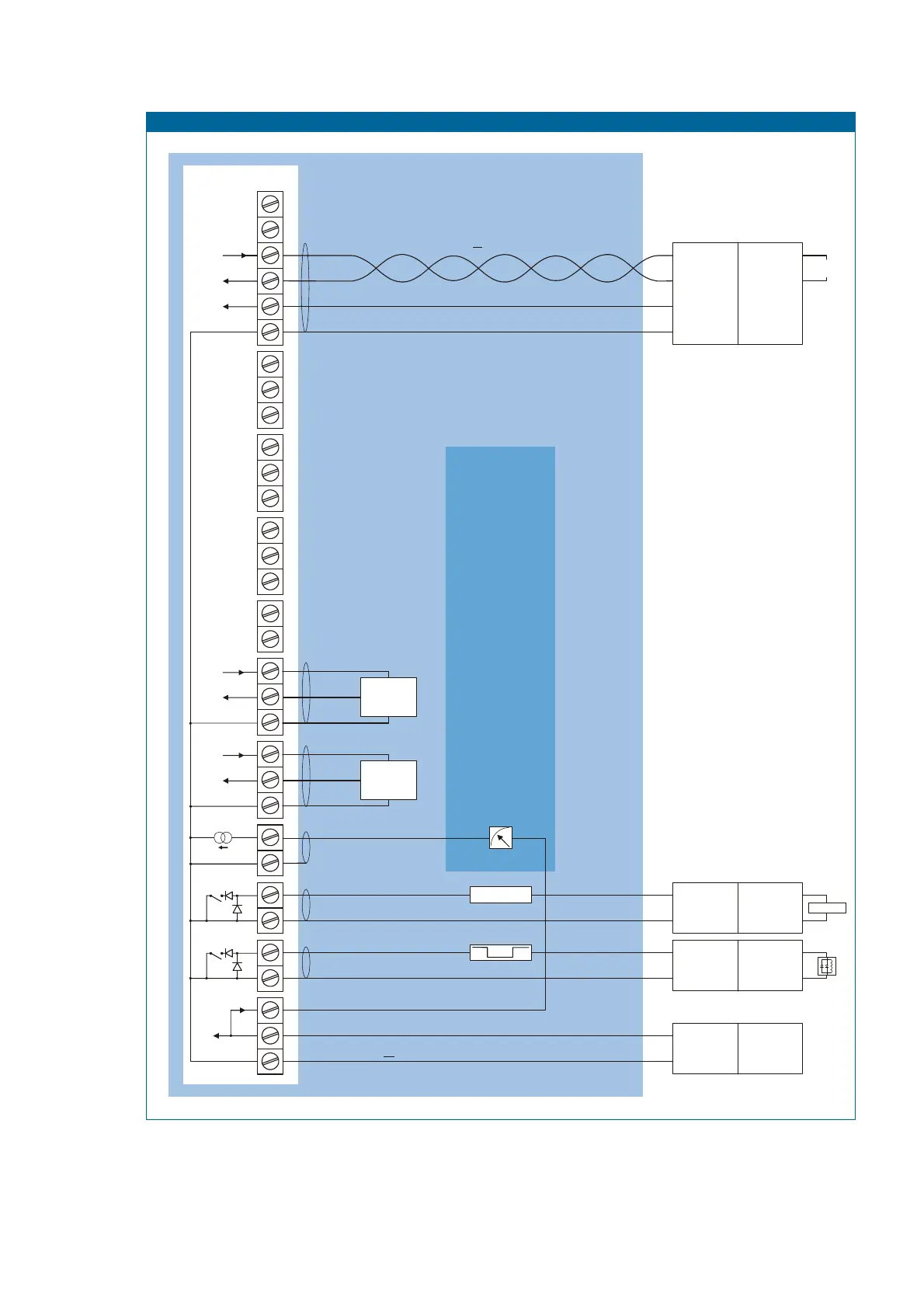
Fig. 15: Configuration example 2 Intrinsically Safe.
TERMINAL CONNECTORS
F100-series
HAZARDOUS AREA
Ci = 17nF
3
4
910
11 12 1 4
13
Common ground
Common ground
Common ground
Common ground
Common ground
Signal
Signal
TOTAL OF ALL CONNECTED
PPARATUS MAY NOT EXCEED
MINUS 17nF
(17nF IS USED BY THE ANALOG
OUTPUT SIGNAL TERMINAL 7+ 8)
Co
66nF
Supply *
Main supply
Circuit depends on
type of signal
Supply *
Circuit depends on
type of signal
Power supply type PD: 16-30V DC
(please note: PD battery supply (type PB) is NOT allowed in IIC applications).and
Flowmeter input
type: P
pulse
Flowmeter input
type: P
pulse
nalog output type AP:
passive 4-20mA
RXD
Common ground
TXD
28
26 29
5
6
Common ground
0
1
27
8
123456
DTR
+12V
27
e.g. counter
e.g. counter
123456
e.g. relay
e.g. PC
e.g. indicator
Modbus communication type CT: TTL
Please note: communciation type CT is allowed in IIC applications.not
* Note power supply type PD: the supply voltage to the sensor is maximum 8.7V (Uo=8.7V Io=25mA Po=150mW)
Configuration example IIB/IIIC and IIC - F115-P-AP-(CT)-OT-PD-XI
Pulse output type OT:
passive transistor
Control output type OT:
passive transistor
Ci is negligibly
small
Ci is negligibly
small
Ci is negligibly
small
Ci is negligibly
small
negative pulse value
Note: above values are safety values.
Consult the technical specification for operational values.
SAFE AREA
Isolator
TTL to:
RS232
RS422
TTL
For example:
MTL5051
I.S. Certified
+
-
+
-
Power supply or
switch interface
For example
MTL5525
MTL5511
= max. 30 V
= max. 100 mA
= max. 0.75 W
Uo
Io
Po
= max. 30 V
= max. 250 mA
= max. 0.85 W
Uo
Io
Po
+
-
Power supply
For example
MTL5525
Uo
Io
Po
= max. 30 V
= max. 100 mA
= max. 0.75 W
+
-
Power supply or
switch interface
For example
MTL5525
MTL5511
= max. 30 V
= max. 100 mA
= max. 0.75 W
Uo
Io
Po
* Note: Communication only allowed when configured as IIB/IIIC.

 Loading...


