HF115PEN_v0501_04
Page 25
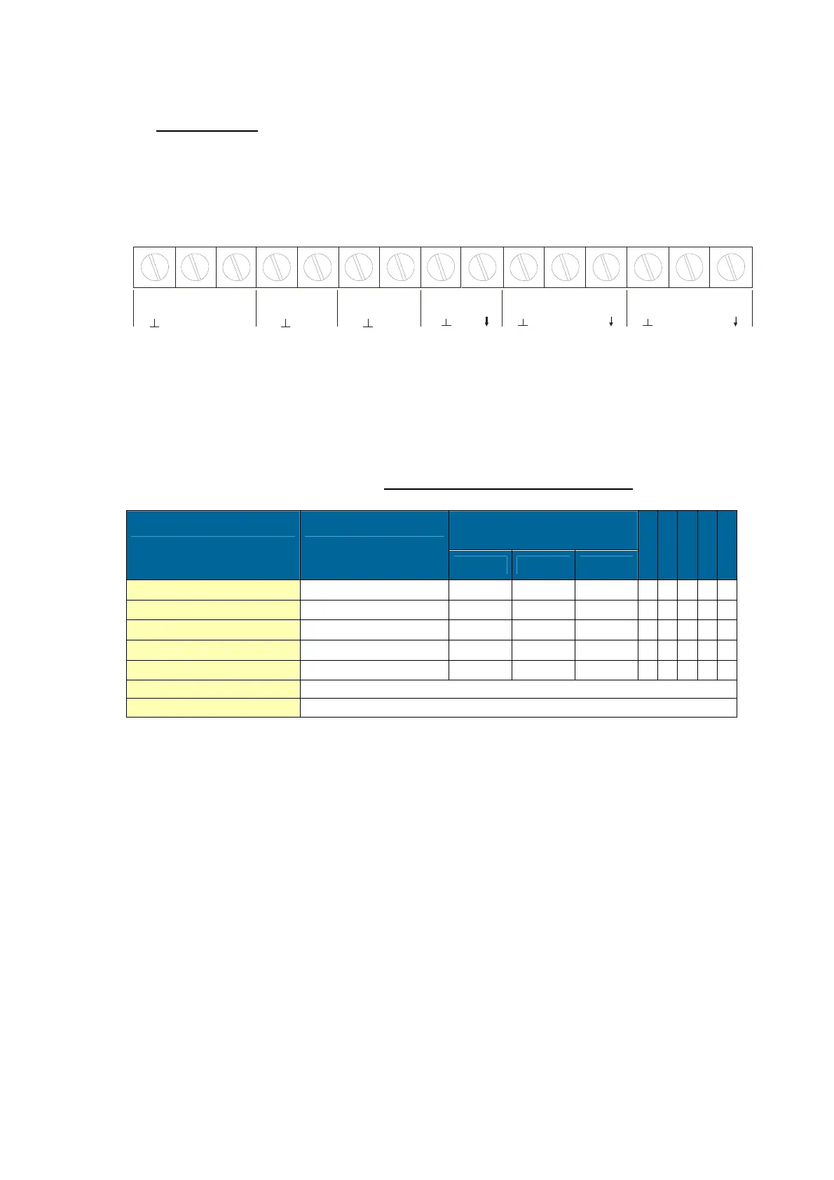
4.4.3. TERMINAL CONNECTORS
For Intrinsically Safe applications: read chapter 5.
The following terminal connectors are available:
Fig. 9: Overview of terminal connectors standard configuration F115-P and options.
REMARKS TERMINAL CONNECTORS:
Terminal GND- 01- 02; power supply - only available with type PD, PF or PM:
TYPE SENSOR SUPPLY
Terminal
TYPE AA
T
A
T
R
GND 01 02
PD 8-24V AC 8,2-12-24V max. 50mA
AC AC
◊ ◊ ◊ ◊
PD 8-30V DC 8,2-12-24V max. 50mA L- L+
◊ ◊ ◊ ◊
PF
24V AC ± 15%
8,2-12-24V max. 400mA
AC AC
◊ ◊ ◊ ◊
PF
24V DC ± 15%
8,2-12-24V max. 400mA L- L+
◊ ◊ ◊ ◊
PM
115-230V AC ± 15%
8,2-12-24V max. 400mA EARTH AC AC
◊ ◊ ◊ ◊ ◊
Note PD
do not use a AC autotransformer (Spartrafo) without a galvanic isolation.
Note PF / PM
The total consumption of the sensors and outputs may not exceed 400mA@24V
◊=option
78
NALOG
OUTPUT
TYPE AA / AB /
AI / AP / AU
GND 1
POWER SUPPLY
TYPE
PD / PF / PM
NL1
2
910
INPUT A
SENSOR SIGNAL
PULSE INPUT
SIGNAL
11
+
126
5
R1 R1
1413
PULSE
OUTPUT R 1
TYPE
OA / OR / OT
SIGNAL +
INPUT B
SENSOR SIGNAL
PULSE INPUT
34
R2
NEGATIVE TOTAL
OUTPUT R 2
TYPE
OA / OR / OT
R2

 Loading...


