HF115PEN_v0501_04
Page 17
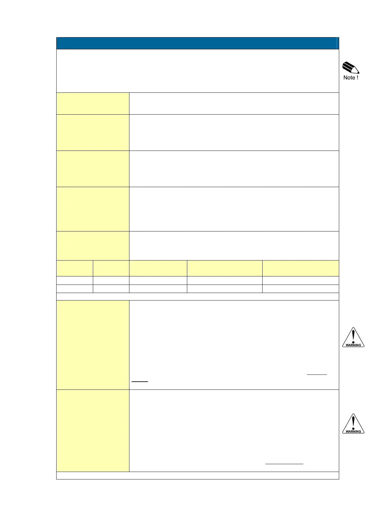
6 - ANALOG OUTPUT
A linear (0)4-20mA or 0-10V signal is generated according to the flowrate with a 10 bits resolution.
The settings for flowrate (SETUP - 2) directly influence the analog output.
Note: When the analog output is not used, please make sure that setting 61 is disabled, or else the
battery life time will be reduced significantly!
When a power supply is available but the output is disabled, a 3.5mA signal will be generated.
The relationship between rate and analog output is set with the following functions:
DISABLE / ENABLE
61
The D/A converter has a relatively high power consumption. If the analog
output is not being used, select "disable" to switch-off the converter.
For more information read par. 4.4.3.
MINIMUM FLOWRATE
62
Enter here the flowrate at which the output should generate a 4mA signal
(or 0mA / 0V) - in most applications at flowrate "zero".
The number of decimals displayed depend upon SETUP 23.
The time and measuring units (L/min for example) are dependant upon
SETUP 21 and 22 but are not displayed.
MAXIMUM FLOWRATE
63
Enter here the flowrate at which the output should generate a 20mA (or
10V) - in most applications at maximum flow.
The number of decimals displayed depend upon SETUP 23.
The time and measuring units (L/min for example) are dependant upon
SETUP 21 and 22 but can not be displayed.
RATE NEGATIVE
64
absolute - ignore
In case a negative flowrate is displayed. it can be set to:
• absolute: a negative flowrate will result in a normal positive analog
output siganl as if it is a positive flow.
• ignore: a negative flowrate results in a minium output value (in most
cases 4mA or 0V).
CUT-OFF
65
To ignore leakage of the flow for example, a low flow cut-off can be set as
a percentage of the full range of 16mA (or 20mA / 10V). When the flow is
less than the required rate, the current will be 4mA.
Examples:
4MA
(SETUP 62)
20MA
(SETUP 63)
CUT-OFF
(SETUP 65)
REQUIRED RATE OUTPUT
0 L/min 100 L/min 2% (100-0)*2% = 2.0 L/min 4+(16*2%) = 4.32mA
20 L/min 800 L/min 3.5% (800-20)*3.5%= 27.3 L/min 4+(16*3.5%)=4.56mA
TUNE MIN / 4MA
66
The initial minimum analog output value is 4mA (or 0mA / 0V). However,
this value might differ slightly due to external influences such as
temperature for example. The 4mA value (or 0mA / 0V) can be tuned
precisely with this setting.
Before tuning the signal, be sure that the analog signal is not
being used for any application!
After pressing PROG, the current will be about 4mA (or 0mA / 0V). The
current can be increased/decreased with the arrow-keys and is directly
active.
Press ENTER to store the new value.
TUNE MAX / 20MA
67
The initial maximum analog output value is 20mA (or 10V). However, this
value might differ slightly due to external influences such as temperature
for example. The 20mA value (or 10V) can be tuned precisely with this
setting.
Before tuning the signal, be sure that the analog signal is not
being used for any application!
After pressing PROG, the current will be about 20mA. The current can be
increased/decreased with the arrow-keys and is directly active. Press
ENTER to store the new value.
Continued next page >>>

 Loading...


