12E
Users Manual
8
Testing Diodes
Warning
To avoid electrical shock or damage to the
Meter when testing diodes in a circuit, make
sure the power to the circuit is turned off and
all capacitors are discharged.
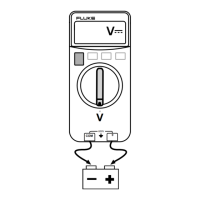
1. Turn the rotary switch to
.
2. Press the YELLOW function button once to activate
Diode Test.
3. Connect the red test lead to the
terminal and the
black test lead to the COM terminal.
4. Connect the red probe to the anode side and the
black test lead to the cathode side of the diode being
tested.
5. Read the forward bias voltage value on the display.
6. If the polarity of the test leads is reversed with diode
polarity, the display reading shows . This can be
used to distinguish the anode and cathode sides of a
diode.
Measuring Capacitance
Caution
To avoid damage to the Meter, disconnect
circuit power and discharge all high-voltage
capacitors before measuring capacitance.
1. Turn the rotary switch to
.
2. Connect the red test lead to the terminal and the
black test lead to the COM terminal.
3. Touch the probes to the capacitor leads.
4. After allowing the reading to stabilize (up to 15
seconds), read the capacitance value on the display.
Maintenance
Beyond replacing batteries and fuses, do not attempt to
repair or service your Meter unless you are qualified to do
so and have the relevant calibration, performance test,
and service instructions. The recommended calibration
cycle is 12 months.