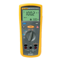
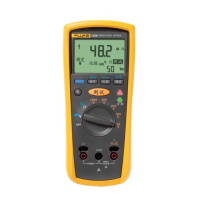
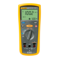
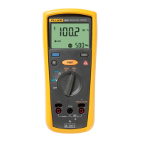
Insulation Tester
Principle of Measurement and Resistance
9
Principle of Measurement and Resistance
The Tester uses these formulas to measure insulation parameters and display the results:
Equipment and Environment
Before you start the verification procedures or make calibration adjustments, refer to this section for the
equipment, system, and setup requirements.
See Table 2 for a list of requirements for the verification tests and calibration adjustment.
Ohm’s Law
Capacitance (Charge)
PI (Polarization Index)
DAR (Dielectric Absorption Ratio)
DD (Dielectric Discharge)
I = current after 1-minute discharge
V = voltage at moment before discharge
C = measured object capacitor
Table 2. Equipment Requirements
Equipment Description
Recommended
Model
Used on:
Verification
Tests
Calibration
Adjustment
High Voltage Meter
3 kV,
±1 %
Fluke 5320A and
Fluke 8846
XX
Current Source
1 nA to 50 nA,
±5 %
50 nA to 400
μA, ±1 %
Keithley 6220
X
Capacitors
0.1
μF, 3 kV, ±10 %
2
μF, 3 kV, ±10 %
WIMA SNMKP Series
XX
Calibrator
DC voltage: -600 V to 600 V
Accuracy:
±0.5 %
AC voltage: 0 V to 600 V
45 Hz to 500 Hz
Accuracy:
±0.5 %
OHM: 0 k
Ω to 60 kΩ
Accuracy: ±0.5 %
Fluke 5522A
XX
Resistors
200 k
Ω to 50 GΩ, 3 kV, ±1 %
500 G
Ω, 3 kV, ±5 %
Combinations of:
OHMITE Slim-Mox Series
and Ultra-Mox Series
X
PC
With serial communication
software
Recommended software:
Tera Term
X
USB Cable (1537 only) USB A to mini B Fluke PN 4499448
X
Probe Fixture (1535 only) See Figure 1.
X
PI
R
10min
R
1min
----------------=
DAR
R
1min
R
15s
--------------=
 Loading...