15B & 17B
Calibration Manual
16
15B Adjustment
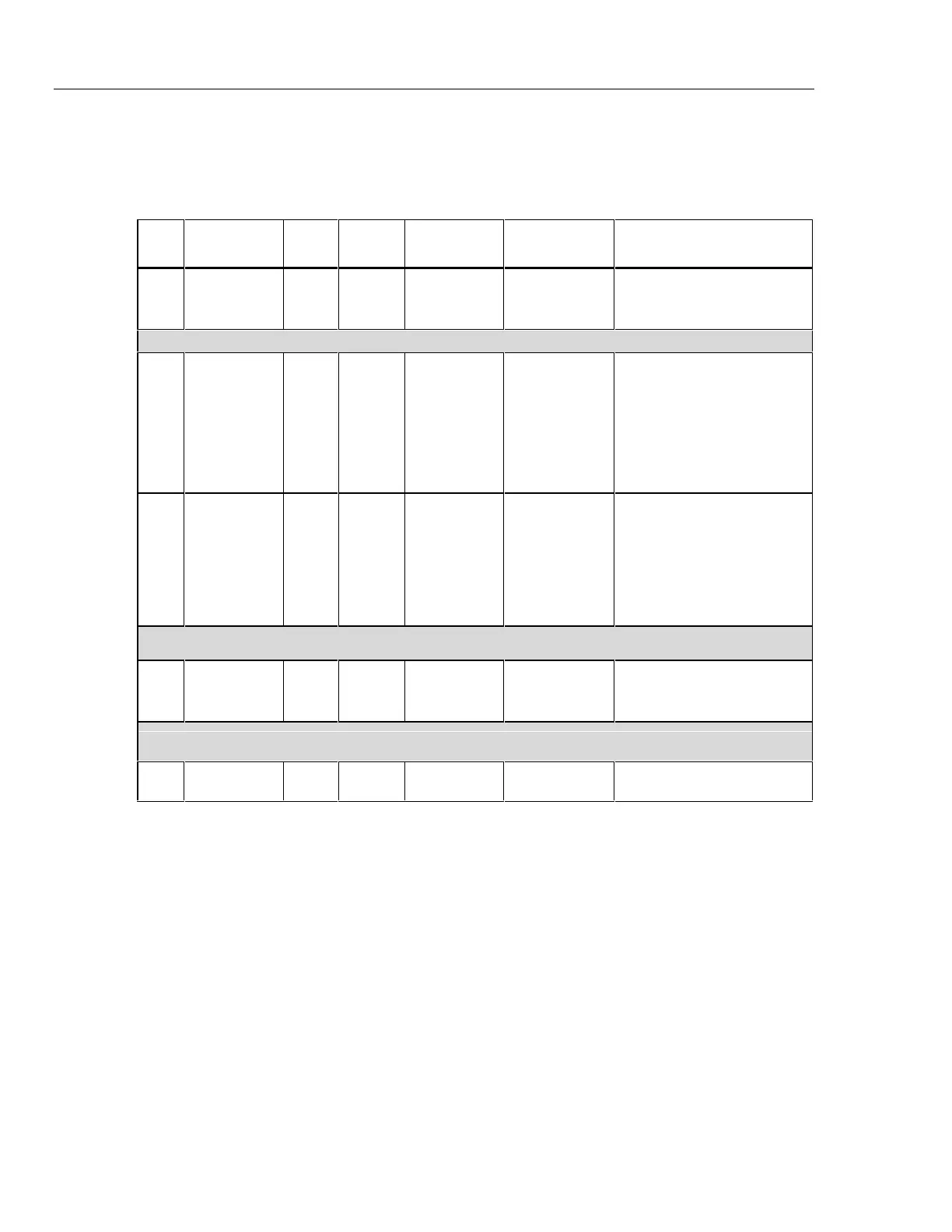
Refer to Table 5 for the 15B adjustment procedure and Figure 3 for the adjustment points.
Table 5. 15B Adjustment
Step
Test
Function
Switch Button Potentiometer 5520 UUT Test Specifications
1
mV dc
Adjustment
M
NO R18 350 mV dc 349.9 to 350.1 mV dc
For step 2, if the display reads between 34.91 and 35.09 V dc, no adjustment is necessary.
2
Volts dc
Adjustment
V NO R18 35 V dc
If the display reads less than
34.91, adjust R18 to
34.91 to 34.92 V dc.
If the display reads more
than 35.09 Adjust R18 to
35.08 to 35.09 V dc.
3
Volts AC
Adjustment
v NO R8 35 V 50 Hz
If step 2 V dc calibration is
less than 35 V dc, adjust R8
to 34.91 to 34.92 V ac.
If step 2 V dc calibration is
equal to or greater than 35 V
dc, adjust R8 to 34.99 to
35.01 V ac.
Set Calibrator to STANDBY.
4
Capacitance
Adjustment
c NO R11 350 nF 349.0 to 351.0 nF
RESET Calibrator
5OFF OFF
 Loading...