Energy Analyzer
Setup
11
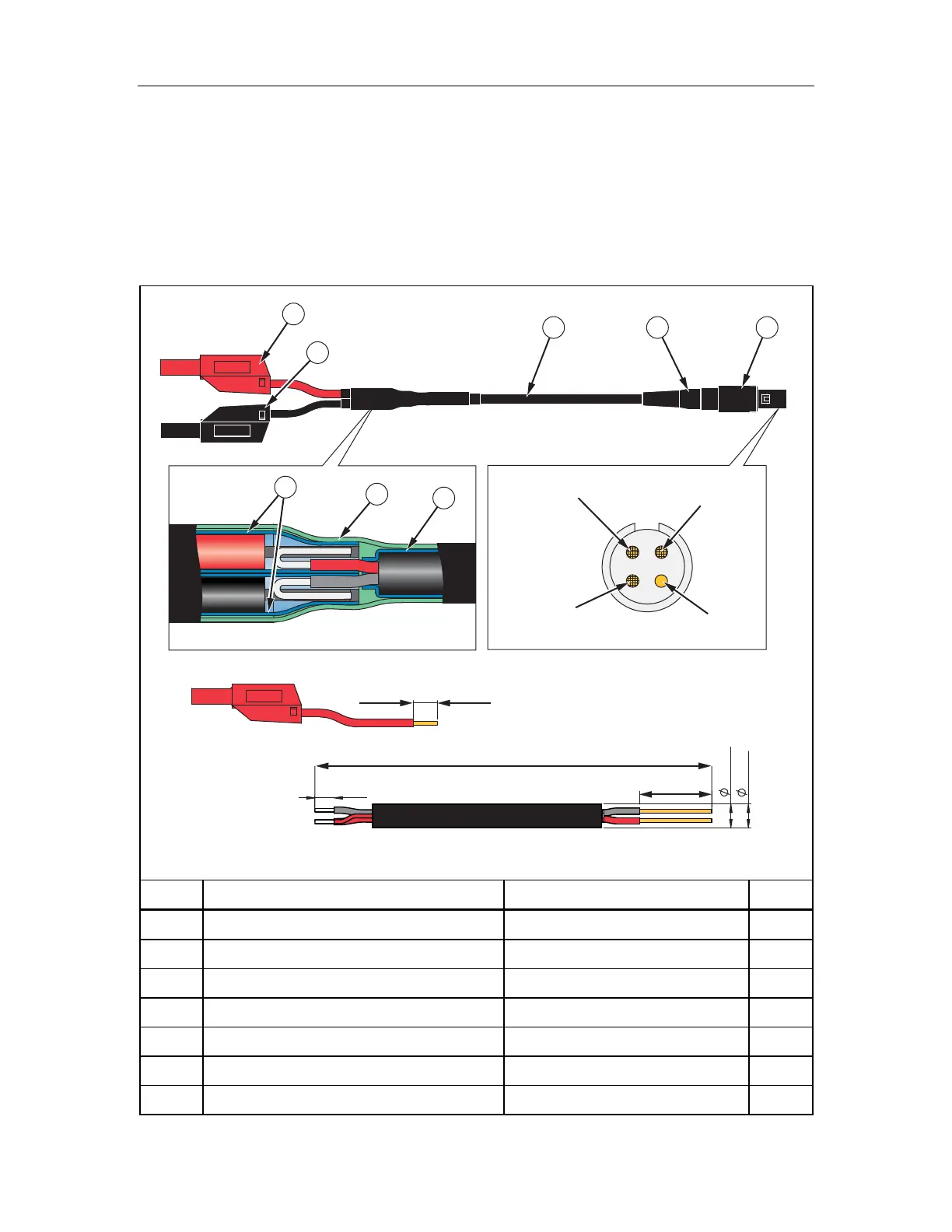
1730 Calibration Cable Assembly
See Table 4 for instructions on how to make the calibration cables.
Caution
Cable must be marked with “max. 30 V to earth.” Any voltage-,
category-, or current-ratings on safety plugs must be removed.
Table 4. 1730 Calibration Cables, Voltage-to-Current-Input
10
+
2
0
1930
±10
15
±1
4
-
0
1
5 max.
4 min.
Screen
(Pin 4)
N.C.
(Pin 3)
Red Wire
(Pin 1)
Black Wire
(Pin 2)
123
4
5
6
7
6
hcf104.eps
Item Description Part Number/Info QTY
Straight Plug, IP50, 4-Pole ODU: S21M08-P04MJG0-528S 1
Cable Bend Relief ODU: 701-023208965-040 1
Signal-Cable, 2x AWG 22-24, shielded ∅4-5 mm (Fluke equiv. # 3803634) 1
Test Lead with 4 mm Safety Plug, stackable red 1
Test Lead with 4 mm Safety Plug, stackable black 1
Heat Shrink Tubing, 2:1 ∅=4.8 mm (3/16”); L=35 mm 3
Heat Shrink Tubing, 3:1, adhesive ∅=12 mm (1/2”); L=60 mm 1