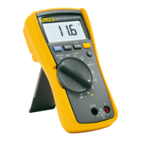
The Fluke 15B MAX/17B MAX Digital Multimeters (the Product) are 6000-count, battery-powered instruments with a digital display, designed for various electrical measurements. Unless otherwise specified, the descriptions and instructions in this manual apply to all versions of the Product, with illustrations primarily showing the 17B MAX.
Function Description
The Product is capable of measuring AC and DC voltage, AC and DC current, resistance, capacitance, frequency, and duty cycle. It also includes a diode test and continuity test function. The 17B MAX model offers additional features such as relative measurements, MIN MAX mode, temperature measurement, and hazardous voltage alert LED.
For voltage measurements, the rotary switch can be set to V, mV, or mV. Users can toggle between mVac or mVdc voltage measurements. The red test lead connects to the V terminal, and the black test lead to the COM terminal. Probes are then touched to the circuit's test points to measure voltage.
For current measurements, the rotary switch is set to mA or A. Users can toggle between ac or dc current measurement. The red test lead connects to the A or mA µA terminal (depending on the current to be measured), and the black test lead to the COM terminal. To measure current, the circuit path must be broken, and the test leads connected across the break before applying power.
Resistance measurements require the rotary switch to be set to the Ohm symbol, and power disconnected from the circuit under test. The red test lead connects to the V terminal, and the black test lead to the COM terminal. Probes are then touched to the desired test points of the circuit.
The continuity test is performed in resistance mode. Pressing the continuity button activates a beeper that sounds continuously if the resistance is less than 70 Ω, indicating a short circuit.
For diode testing, the rotary switch is set to the diode symbol. Pressing the diode test button twice activates the Diode Test. The red test lead connects to the V terminal, and the black test lead to the COM terminal. The red probe connects to the anode side, and the black test lead to the cathode side of the diode under test. The display shows the forward bias voltage value. If the polarity is reversed, the display shows OL, which helps distinguish anode and cathode sides.
Capacitance measurements are performed by setting the rotary switch to the capacitance symbol. The red test lead connects to the V terminal, and the black test lead to the COM terminal. Probes are touched to the capacitor leads, and the indication is allowed to stabilize before reading the capacitance value. It is crucial to disconnect circuit power and discharge all high-voltage capacitors before measuring capacitance to prevent damage.
The 17B MAX model also supports temperature measurement using a K-type thermocouple. The rotary switch is set to the temperature symbol. The K-type thermocouple plug marked '+' is plugged into the V terminal, and the other plug into the COM terminal.
Frequency and duty cycle measurements (17B MAX only) can be performed while making voltage or current measurements. Pressing the Hz % button changes the Product to frequency or duty cycle mode. The display shows the frequency of the signal. Pressing Hz % again makes a duty cycle measurement, showing the percent of duty cycle.
Usage Features
The Product includes several features to enhance usability and safety:
- Auto Sleep: The Product automatically enters sleep mode after 20 minutes of inactivity to conserve battery life. It can be woken by pressing any keypad button. The Auto Sleep function can be disabled by holding down the power button while turning on the Product until "PoFF" is displayed. Disabling Auto Sleep also disables the Auto Backlight Off function.
- Auto Backlight Off: The backlight automatically turns off after 2 minutes of inactivity. It can be disabled by holding down the backlight button while turning on the Product until "LoFF" is displayed.
- Manual and Auto Range Selection: The Product offers both manual and auto range options. In Auto Range mode, the Product automatically selects the best range for the input detected, eliminating the need to reset the range when switching test points. Manual Range mode can be entered by pressing the RANGE button. Each press of RANGE increments the range, cycling back to the lowest range after reaching the highest. To exit Manual Range mode, hold RANGE for 2 seconds.
- Data Hold: The HOLD function allows users to freeze the current reading on the display. This is activated by pressing the HOLD button and deactivated by pressing it again. A warning is provided against using HOLD to measure unknown potentials, as the display will not change when a different potential is measured.
- Relative Measurements (17B MAX only): This feature allows for relative measurements in all functions except frequency, resistance, continuity, duty cycle, and diode. To use it, the Product is set to the desired function, and test leads are touched to the circuit to establish a reference value. Pressing REL stores this value and activates relative measurement mode, displaying the difference between the reference and subsequent readings. Pressing REL again returns to normal operation.
- MIN MAX Mode (17B MAX Only): Available for all functions except resistance, capacitance, frequency, duty cycle, and diode, this mode allows users to capture minimum and maximum readings. Pressing MIN MAX once sets the Product to MAX mode, and pressing it again sets it to MIN mode. Holding MIN MAX for 2 seconds returns to normal operation.
- Input Alert™ Feature: This safety feature prevents circuit damage and blown fuses. If a test lead is plugged into a current terminal (mA/µA or A) but the rotary switch is not set to the correct current position, the beeper chirps, the hazardous voltage alert LED (17B MAX only) illuminates, and the HOLD and RANGE buttons rapidly flash. This alerts the user to avoid attempting voltage, continuity, resistance, capacitance, or diode measurements with leads in current terminals. To prevent false warnings, the mA/µA and A terminals should be kept free of metallic debris.
- Hazardous Voltage Alert LED (17B MAX only): This LED illuminates when the Product detects ≥30 V or a voltage overload (OL), warning the user of potentially hazardous voltage. It also illuminates during Frequency/Duty cycle tests when the Product is in ac or dc volt or millivolt modes.
Maintenance Features
Routine maintenance ensures the Product's longevity and accurate operation:
- General Maintenance: The case should be periodically wiped with a damp cloth and mild detergent. Abrasives or solvents should not be used. Dirt or moisture in the terminals can affect readings. To clean the terminals, turn off the Product, remove test leads, shake out any dirt, and then use a swab soaked in isopropyl alcohol to clean the inside of each input terminal.
- Test Fuses: To test the fuses, turn the rotary switch to the continuity/resistance symbol. Plug a test lead into the A or mA µA terminal and touch the probe to the V terminal. A good A terminal fuse reads <0.5 Ω, and a good mA µA terminal fuse reads <10 KΩ. If the display reads OL, the fuse needs replacement. If any other value is shown, the Product should be serviced.
- Replace Batteries and Fuses: A warning is provided to replace batteries as soon as the battery indicator appears to prevent false readings, which could lead to electric shock or personal injury. Only replacement fuses with the specified amperage, voltage, and interrupt ratings should be installed to prevent damage or injury. Test leads must be disconnected before opening the case or battery door. Old devices should be disposed of professionally and environmentally soundly, including deleting personal data and removing batteries for separate disposal.
- Service and Parts: If the Product fails, users should first ensure batteries are charged, test the fuses, and review the manual for correct operation. Replacement parts are listed in a table, including battery, battery door assembly, various test leads (TL31 with two caps and fine tips, TL75 with two caps), fuses (0.440 A, 1000 V, FAST and 11 A, 1000 V, FAST), and a holster.
- TL31 Test Leads: The TL31 Test Leads, which come with certain Product models, have fine tips for testing small components. They can be used for CAT III applications when the protective cap is properly installed. Users are warned not to use damaged test leads (exposed metal, damaged insulation, or visible wear indicator) and to check test lead continuity. Caution is advised when using test leads, and the protective cap should be installed to prevent injury.
- Test Small Components in Circuit: To test small components, protective caps are pushed up from the bottom with a thumb to remove them. Fluke recommends clamping the caps on the test cables close to the DMM. Bare tips are then connected to small components for measurement. After testing, the protective caps are reinstalled.
- Test CAT III Applications: For CAT III applications, protective caps are twisted and pushed firmly onto the lead body until the probe end comes out of the cap. A warning advises against pushing the protective cap onto the lead body with a thumb to prevent personal injury. After testing, the cap is pushed back up to hide the tip and reinstall the protective caps.
Beyond battery and fuse replacement, users are advised not to attempt to repair or service the Product unless qualified, with relevant calibration, performance test, and service instructions. The recommended calibration cycle is 12 months. For safe operation and maintenance, users should refer to the Safety Information document.