Digital Multimeters
Measurements
9
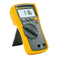
Te s t fo r C o n t i n u i t y
To t e s t f o r c o n t i n u i t y :
1. Select resistance mode.
2. Push Bonce to activate the continuity beeper. If the
resistance is <70
Ω, the beeper sounds continuously
which designates a short circuit. See Figure 6.
Figure 6. Measure Resistance and Continuity
Te s t D i od e s
W Caution
To prevent possible damage to the Product or to
the equipment under test, disconnect circuit
power and discharge all high-voltage capacitors
before you test diodes.
To t e s t a d i o d e :
1. Turn the rotary switch to Q.
2. Push B twice to activate Diode Test.
3. Connect the red test lead to the W terminal and the
black test lead to the COM terminal.
4. Connect the red probe to the anode side and the black
test lead to the cathode side of the diode under test.
5. See the display for the forward bias voltage value.
6. If you reverse the polarity of the test leads with diode
polarity, the display reading shows OL. Use this reading
to distinguish the anode and cathode sides of a diode.
<70