341
A
343A
above
the
meter. The lamps
are easily removeable
without
special tools.
The
two control circuit lamps,
DS1 and
DS2
are located on the main
circuit board and are accessible
after removing the top cover.
4-24. PERFORMANCE
TESTS
4-25. Performance tests consist
of
line regulation,
load
regulation, ripple, and output voltage accuracy
tests, and
are designed to compare
instrument
performance to speci-
fications. The tests may be used during maintenance or for
receiving inspection.
Test should be performed under
standard test conditions: ambient temperature
23 ±
1°
C,
relative humidity less than 70%. Allow instrument
to warm
up for at least
1
hour before testing.
An instrument that
fails any of the performance tests may require
corrective
maintenance
or
calibration.
In
case
of trouble, analysis
of
the
tests
results,
with reference to the
troubleshooting
section, should help to locate the trouble.
NOTE!
Unless otherwise
specified, the following
tests
apply to
both Model 341
A and Model 343A
instruments.
4-26.
LINE
REGULATION
4-27.
The line regulation test
determines whether
the
output voltage
of the instrument will
remain constant,
within specified limits,
for low and high line
voltages.
a. Connect the autotransformer
to the line, and connect
the Model
341 A to the autotransformer. Adjust
the
autotransformer for
1 15
volts
output.
b. Set the Model
341 A/343
A
controls
as follows:
FUNCTION
STANDBY/RESET
e. Vary the line voltage
from 115 volts
to 103.5 volts.
The
895A
should
indicate
a
voltage
change
of less
than
30 microvolts.
f. Vary the line voltage
from 1
15
volts
to 126.5
volts.
The 895 A should
indicate
a
voltage
change
of less
than 30 microvolts.
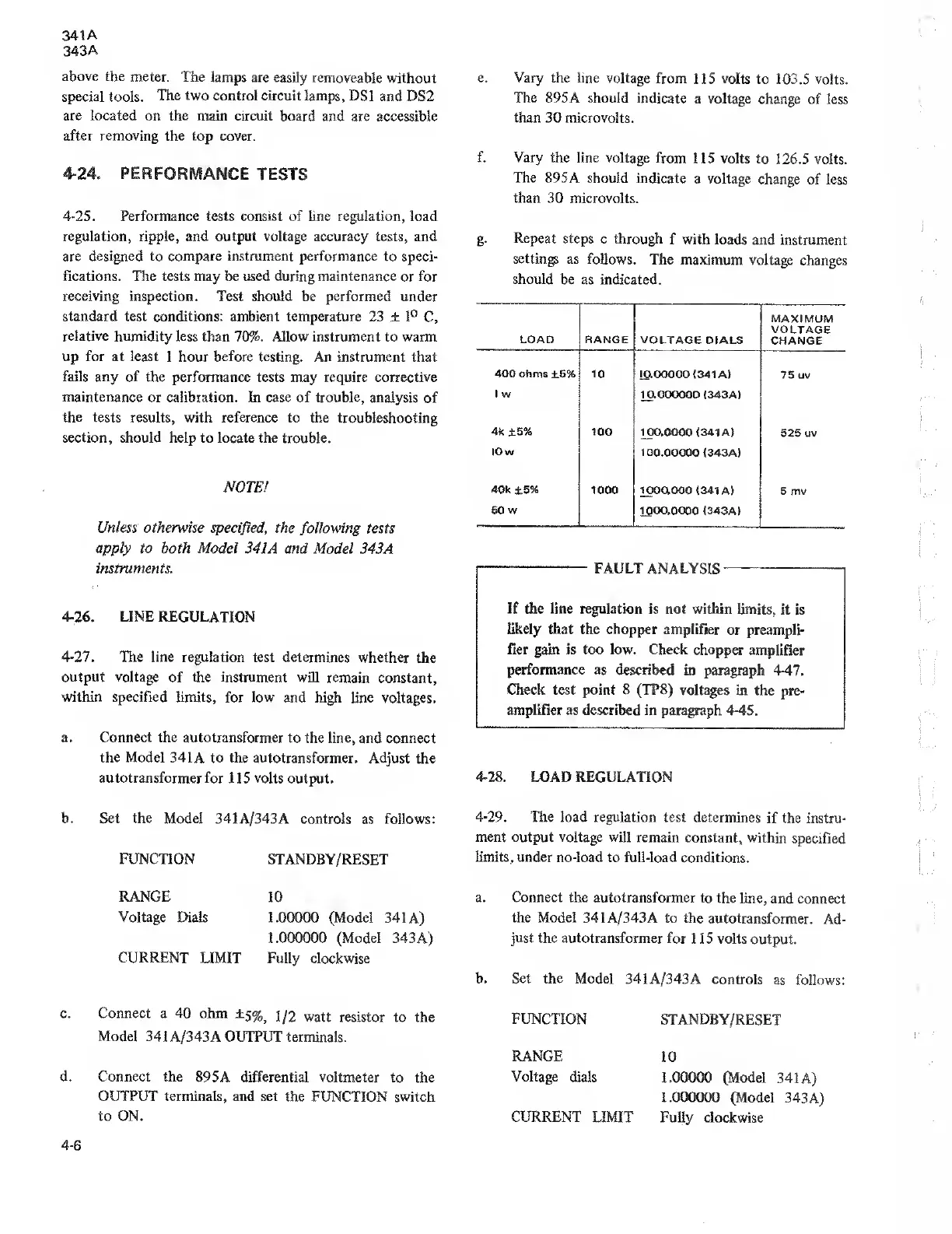
g.
Repeat steps
c through f with
loads and
instrument
settings as follows.
The maximum voltage
changes
should be
as indicated.
LOAD RANGE VOLTAGE DIALS
MAXIMUM
VOLTAGE
CHANGE
400 ohms ±6% 10 10.00000
(341 A)
75 uv
1 w
10.000000 (343A)
4k ±5% 100
100.0000 (341 A)
525 uv
10 w
100.00000 (343
A)
40k
±5% 1000 1000.000
(341 A)
5 mv
50 w
1000.0000 (343A)
FAULT ANALYSIS
If
the line regulation is not within
limits, it
is
likely that the chopper amplifier
or preampli-
fier
gain
is too low. Check
chopper amplifier
performance as
described in paragraph
447.
Check test point
8
(TP8
)
voltages in
the pre-
amplifier as described in
paragraph 4 45.
4-28.
LOAD REGULATION
4-29.
The load regulation test
determines
if the instru-
ment output voltage will
remain
constant, within
specified
limits, under
no-load to full-load
conditions.
RANGE
Voltage
Dials
CURRENT
LIMIT
10
1.00000 (Model 341
A)
1.000000 (Model
343
A)
Fully clockwise
a. Connect the
autotransformer to
the line, and
connect
the Model
341 A/343A to the
autotransformer.
Ad-
just
the autotransformer for
1 1 5 volts
output.
b. Set the Model
341A/343A controls
as follows:
c. Connect a 40 ohm
±
5%
5
1/2
watt resistor to the
Model
341A/343A OUTPUT terminals.
d. Connect the
895A differential voltmeter
to the
OUTPUT terminals, and set
the FUNCTION switch
to ON.
FUNCTION
STANDBY/RESET
RANGE
Voltage
dials
CURRENT
LIMIT
10
1.00000 (Model
341
A)
1.000000
(Model
343A)
Fully
clockwise
4-6