341
A
343A
c.
Jumper the
SENSE
terminals to
the output terminals.
d.
Connect
the 895 A
differential
voltmeter to the
SENSE
terminals,
and set the
FUNCTION
switch to
ON.
e.
Record the
voltage indicated by
the 895
A.
l.
Connect a
40k
±5%,
50
watt resistor to
the OUTPUT
terminals.
The
895
A should
indicate a
voltage change
of less
than 5
millivolts.
m.
Repeat
steps a.
through m. for line
voltages of 103.5
volts
ac and
126.5 volts ac.
f.
Connect a
40 ohm
±5%,
1/2
watt
resistor to the
OUTPUT
terminals. The
voltmeter should
indicate
a
voltage change of
less than 30
microvolts.
g.
Remove the 40 ohm
resistor, and set
the voltage
dials
to 10.00000
(10.000000 for
the Model 343A).
Record
the voltage
indicated
by
the
895
A.
h.
Connect
a
400
ohm
±5%,
1 watt
resistor to the
OUTPUT
terminals.
The 895 A should
indicate a
voltage
change of less than 75
microvolts.
i.
Remove the 400
ohm resistor.
Set the RANGE
switch
to
100
and the voltage dials
to 100.0000
(100.00000
on
Model 343A).
Record the
voltage
indicated by
the 895A.
j.
Connect a 4k ±5
%,
10
watt resistor to
the OUTPUT
terminals.
The 895A should
indicate a
voltage change
of less than 525
microvolts.
k.
Remove the 4 k
resistor. Set the
RANGE switch to
1000 and the
voltage dials to 1000
.Q00
(1000.0000
on the Model 343
A).
Record the
voltage indicated
by the 895 A.
FAULT ANALYSIS
If load
regulation is
poor, check for proper
operation of
the preamplifier and
chopper
amplifier as
described in
paragraph
4-45
and
4-47.
Also,
ensure that
SENSE terminals are
connected properly. See
paragraph
2-14.
4-30. RIPPLE
4-31.
The
ripple test determines if
the
ac
ripple present
on the
instrument dc
output is within specified limits.
a.
Install top and
bottom instrument
covers,
and
con-
nect
+
OUTPUT to chassis
ground.
b.
Connect the
preamplifier to the OUTPUT terminals,
and
connect the 93 IB true rms
voltmeter to the
output
of
the preamplifier.
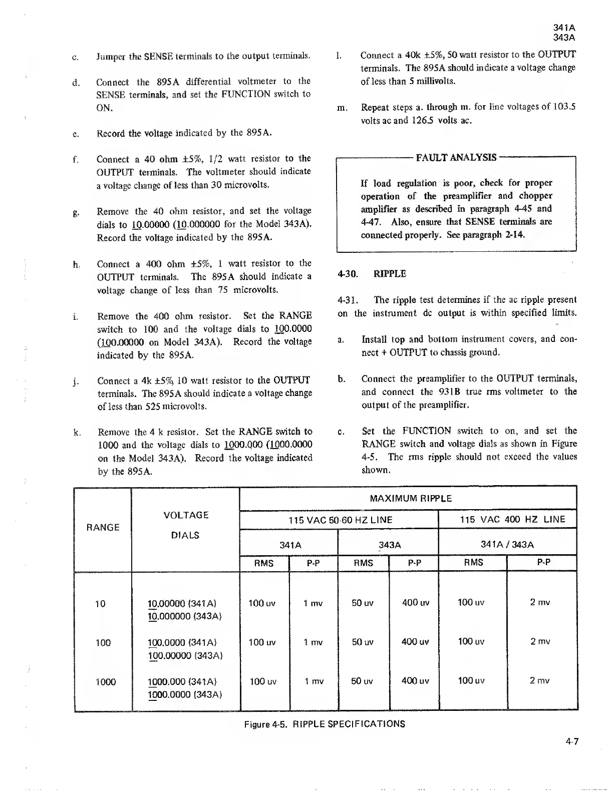
c.
Set the FUNCTION
switch to on, and set the
RANGE switch
and voltage dials as shown in
Figure
4-5.
The rms
ripple should not
exceed
the
values
shown.
RANGE
VOLTAGE
DIALS
MAXIMUM RIPPLE
115
VAC
50-60
HZ
LINE 115
VAC 400 HZ
LINE
341A 343A
341
A
/ 343
A
RMS P-P
RMS
EBB
RMS
P-P
10 10.00000
{341 A)
100 uv 1 mv
50 uv
400 uv 100
uv 2 mv
10.000000
(343A)
100 100.0000
(341 A) 100
uv 1 mv 50
uv 400
uv 100 uv 2
mv
100.00000
(343
A)
1000
1000.000 (341
A) 100
uv
1 mv
50 uv
400 uv 100
uv 2
mv
1000.0000
(343A)
Figure
4-5.
RIPPLE
SPECIFICATIONS
4-7