FAULT
ANALYSIS
If there
are errors in test point resistance
read-
ings,
check the following components.
TEST POINT
SENSE
Defective diode CM
7
Defective
transistor
Q6
t
Oil
Defective transistor
Q9,
Q1I, or
Q18
Defective
diode CRi,
CR2, CRB, CR4 or
CR5
Defective diode CR26
or CR27
Defective lamp DS5,
DS6 or
DS7
Defective
capacitor €54
Shorted relay K2A
and
K3A
Resistor R369 changed
value
4-41.
STANDBY
TEST
4-42.
This test
determines instrument
power
consump-
tion and verifies proper operation of the controlled current
Limiter under standby conditions,
a. Set Model 341 A/343A
controls as follows:
FUNCTION
OFF
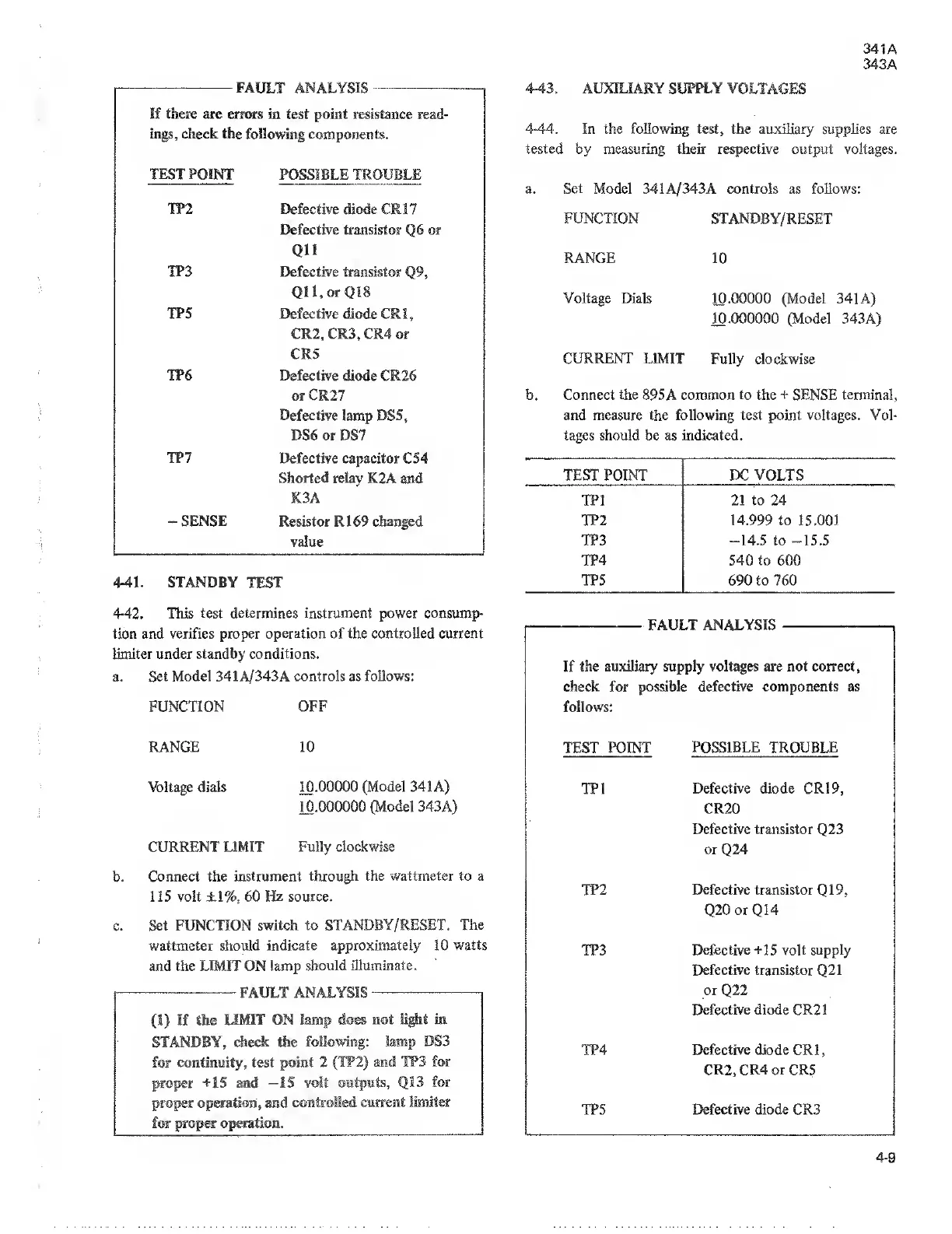
4-43.
AUXILIARY
SUPPLY
VOLTAGES
In the
following
test, the auxiliary supplies are
by
measuring their respective
output voltages.
FUNCTION
RANGE
Voltage Dials
341A/343A
controls
as follows:
STANDBY/RESET
10.00000 (Model 341 A)
10.000000 (Model 343A)
CURRENT LIMIT Fully
clockwise
Connect
the
895A
common to the +
SENSE
terminal,
and measure
the following test
point voltages. Vol-
tages should
be
as
indicated.
TEST POINT PC VOLTS
21
to 24
14.999 to 15.001
-14.5
to
-15.5
540
to 600
690 to
760
FAULT ANALYSIS
If the auxiliary supply
voltages are not correct,
check for possible defective
components as
follows:
RANGE
TEST POINT
POSSIBLE TROUBLE
Voltage dials 10.00000
(Model 341 A)
10.000000
(Model
343A)
CURRENT LIMIT
Fully clockwise
Connect the instrument
through the wattmeter to a
1 15 volt
±1%,
60
Hz
source.
Set FUNCTION
switch to STANDBY/RESET.
The
wattmeter should
indicate approximately 10
watts
and the LIMIT ON lamp
should illuminate,
FAULT
ANALYSIS
,
(1)
If the
LIMIT ON
lamp
STANDBY,
check
the
folic
for continuity, test point 2
proper
+15
and
—IS volt
proper
operation,
and
contro
Defective diode CR19,
CR20
Defective transistor
Q23
or
Q24
Defective transistor
Q19,
Q20
or
Q14
Defective +15 volt supply
Defective transistor
Q21
or
Q22
Defective diode CR2
1
Defective diode
CRI
,
CR2,
CR4
or CR5
Defective diode CR3