341
A
343A
4-45.
POWER-ON
TEST
4-46. This test
determines instrument power
consump-
tion
under
power-on conditions and
verifies proper
opera-
tion of the chopper-stab
iiized amplifier.
a.
Set
Model
341A/343A control as follows:
FUNCTION
OFF
RANGE 10
Voltage dials
10.00000
(Model 341
A)
10.000000 (Model
343A)
CURRENT LIMIT
Fully clockwise
b. Connect the instrument
through the
wattmeter to
a
115 volt
±1%,
60 Hz source.
(3)
If the LIMIT ON lamp does
not
extinguish
in FUNCTION-ON position,
check the high
voltage fuse
F2,
check
for proper control
circuit operation,
and
check
controlled
current
limiter operation, paragraph 4-51.
(4)
If the
output voltage is not within
limits,
check as described
in paragraph 4-34 (paragraph
4-35
for the Mode!
343A).
4-47.
CHOPPER AMPLIFIER
;
0)U
4-48.
This test verifies proper
chopper amplifier
opera-
tion
by examining
multivibrator
and
chopper amplifier
signal characteristics.
a. Set Model 341
A/343 A controls as follows:
c. Set FUNCTION
switch to'
STANDBY/RESET.
FUNCTION
ON
d. Measure the voltage
at TP8
with the
895A, using
+ SENSE as
common. The voltmeter
should
indicate
between
—
1
.7
and
-2.1
volts.
e. Set FUNCTION switch to ON. The wattmeter
should
indicate approximately
15 watts and the LIMIT ON
lamp should
extinguish.
f.
Repeat
step d. The
895A should
indicate between
+2.3
and +2.7 volts.
RANGE
10
Voltage
dials
10.00000 (Model
341 A)
10.000000
(Model
343A)
CURRENT
LIMIT
Fully clockwise
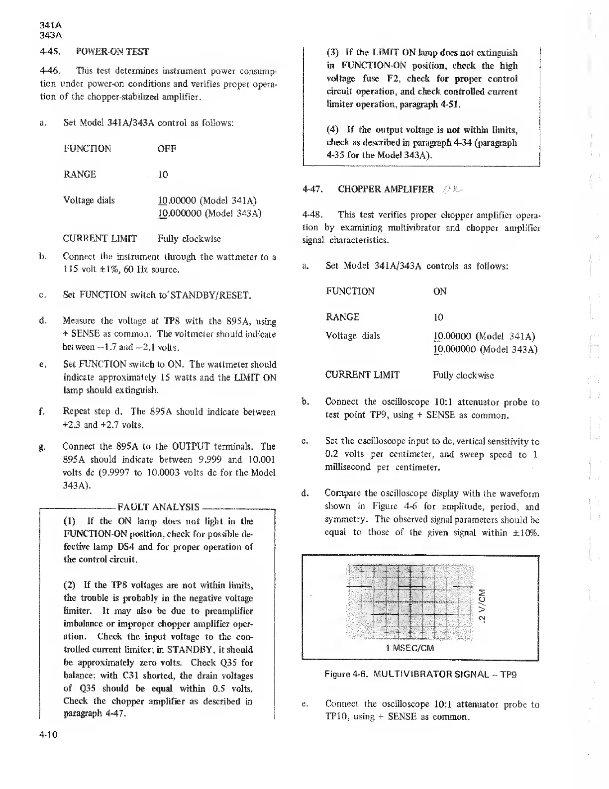
b. Connect the oscilloscope
10:1 attenuator
probe to
test
point TP9, using + SENSE
as common.
g.
Connect the
895A
to the OUTPUT terminals.
The
895 A
should
indicate
between
9.999 and 10.001
volts dc (9.9997 to 10.0003 volts dc for the
Model
343 A).
FAULT ANALYSIS
(1)
If the ON lamp
does not light in the
FUNCTION-ON position, check
for
possible
de-
fective
lamp DS4 and for proper operation of
the control circuit.
(2)
If the
TPS voltages are not within limits,
the trouble
is probably in the negative voltage
limiter. It
may also be due
to
preamplifier
imbalance or improper
chopper amplifier oper-
ation. Check the input
voltage to the con-
trolled current limiter;
in STANDBY, it should
be approximately
zero volts. Check
Q35 for
balance;
with C31 shorted,
the drain voltages
of
Q35
should
be equal within 0.5 volts.
Check the chopper
amplifier as described
in
paragraph 4-47.
c. Set the oscilloscope
input to dc,
vertical sensitivity
to
0.2
volts
per centimeter,
and sweep
speed to 1
millisecond per centimeter.
d. Compare the oscilloscope
display with
the waveform
shown
in
Figure
4-6
for amplitude,
period,
and
symmetry.
The observed
signal parameters
should
be
equal to those of the
given signal
within
±10%.
1
MSEC/CM
Figure
4-6.
MULTIVIBRATOR
SIGNAL
-
TP9
e. Connect the
oscilloscope
10:1
attenuator
probe
to
TP
10,
using
+
SENSE
as common.
4-10