360
AC Leakage Current Clamp Meter
8
Table 4. Calibration Adjustment Steps
Step Selected Range Wire Coils Calibrator Output Adjustment Adjustment Limits
1 30 A 2 13.5, 60 Hz VR1 26.97 to 27.03
2 3 mA, 60 Hz VR6 2.998 to 3.002
3
20 mA, 50 Hz
20 mA, 60 Hz
VR5
Adjust VR5 for same
reading at 50 and 60 Hz
4 0.008 mA, 60 Hz VR7 0.000 to 0.005 mA
5
mA None
0.012 mA, 60 Hz N/A 0.009 to 0.012 mA
Not Used
VR7
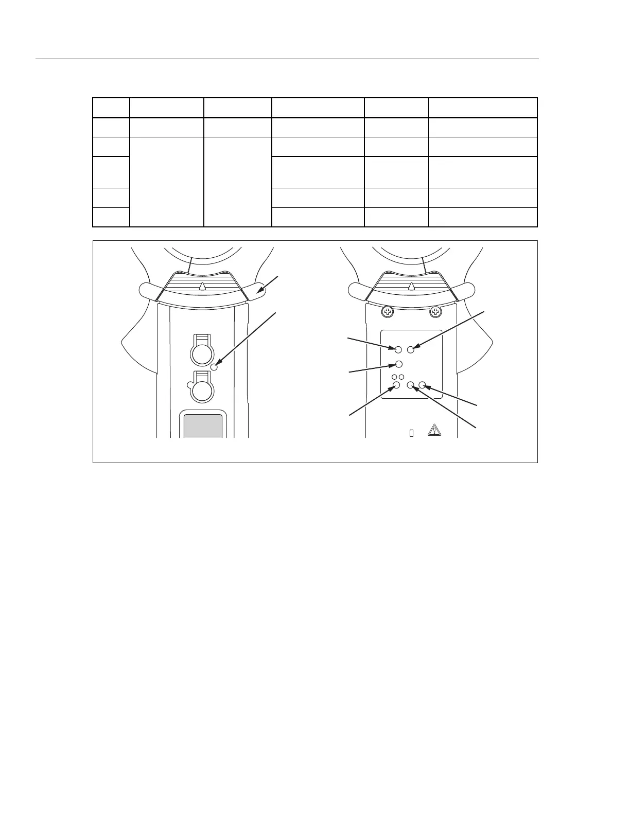
VR1
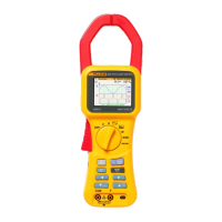
Front View Back View
VR6
VR5
Not Used
Not Used
Tactile Barrier
fcx02.eps
Figure 3. Adjustment Locations
The calibration adjustment is complete.