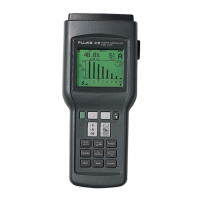
39/41B
Service Manual
2-14
Specifications:
• x 128 pixels (W x H)
• FSTN (Film-Compensated Super Twisted Nematic)
• LED backlight
• 32K x 8 display RAM
• Integrated 1335 controller
2-41. BackLight
The backlight is a series of 24 yellow-green Light Emitting Diodes (LEDs). The diodes
are connected two in series and 12 in parallel. The backlight control circuit switches the
current and sets the level of the current to the diodes. Q15, R51, R55, R57, and R60 form
a level shifter to turn on control transistor Q16. When Q16 turns on, it establishes a
reference voltage of 100 mV at the noninverting input of U21. U21 through Q14 forces
100 mV across the parallel combination of R54 and R59. This action causes the current
through the back light to be ≈40 mA.
2-42. Contrast Control - EEPOT (U8)
The Contrast Control EEPOT is functionally the same as a regular potentiometer, except
that the wiper location is controlled via a digital interface instead of a knob. The digital
interface to this part consists of three lines, chip select (CS), increment wiper (INC*),
and up/down (U/D*). To adjust the potentiometer, CS is brought low and the INC line is
strobed. The direction of the wiper is dependent on the state of the U/D* pin. U8 is
configured as a simple voltage divider and controls the voltage supplied to the LCD
module. This voltage varies from about -13V dc to -20V dc. The EEPOT setting is also
stored to serial EEPROM (U22). If an invalid EEPOT value is read from the serial
EEPROM, a default value is used. If a too light value is read, a minimum contrast value
is used.
2-43. Optical Interface (Model 41B Only)
This interface consists of two main sections: the receiver and the transmitter. Data going
out of the unit is transmitted through a infrared LED. Incoming data is captured through
a photo transistor in the receiver.
2-44. Transmitter
CR6 is an infrared emitter used to communicate with an optical RS-232 interface cable
provided with the Fluke 41B. The transmitter circuit is a simple level shifter used to
provide more current to the LED, than the DSP can provide directly. Q21 is used as a
current switch to turn CR6 on and off. When TXD on the microcontroller goes low, Q21
turns on, and the current through CR6 is set by the resistor R36 and the voltage across
CR6. The current through CR6 should be ≈11 mA at ambient.
2-45. Receiver
Q5 is a photo transistor used to receive the signal provided by the Fluke 41B’s RS-232
cable. It senses the infrared light from the infrared LED in the optional interface cable.
When an infrared light source is on, Q5 begins to conduct harder, which turns on Q1. Q1
provides the necessary current gain to interface the received signal with the
microcontroller. U20 provides a variable collector supply voltage to Q5. R25 and C10
filter the signal at the collector of Q1. The DC value of the signal is compared with the
diode voltage of CR1. U20 integrates the error voltage and sets the voltage at the
collector of Q5. C11 is an additional filter for the collector voltage of Q5. The voltage at
the collector of Q5 is ≈2V dc with no light and should go to 0V dc if light is shown
continuously on Q5.

 Loading...