Performance Testing and Calibration
Calibrating the Tester
4
4-11
Table 4-6. Harmonics Performance for Amps
Fluke 5500A Output
Fluke
Tester
Performance Limits
Amplitude PhaseAmplitude
(mV)
Harmonic
No.
Phase
(deg.)
Harmonic
Cursor No.
Min Max Min Max
20.00 1 10.00 1 19.1 20.9 8 12
20.00 3 20.00 3 19.1 20.9 14 26
20.00 9 30.00 9 19.1 20.9 21 39
20.00 13 40.00 13 19.1 20.9 29 51
20.00 21 50.00 21 18.7 21.3 35 65
20.00 31 60.00 31 18.1 21.9 40 80
4-13. Testing Serial I/O Performance (Model 41B Only)
Confirming serial I/O performance requires the RS-232 optical interface cable,
FlukeView™ software, and a PC running Window 3.1. If not already done, install the
FlukeView™ software on the PC and configure for the appropriate serial port.
1. Connect the optical interface cable between the optical interface on the side of the
Tester and the serial port of the PC.
Note
The correct serial port on the PC will be determined by the configuration
of the PC and installation of the FlukeView™ software.
2. Open FlukeView™ software on the PC.
3. Turn on the Tester.
4. From the FlukeView™ toolbar, choose the camera icon.
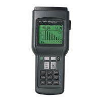
5. Communication over the serial I/O port is confirmed when the picture window on
the PC, displays a picture of the Tester’s display with the appropriate values and/or
waveform.
6. To confirm the print function, press the Print button and confirm the Tester displays
“PRNT” in the upper left corner of the display and the following message appears:
* PRINTING *
PRESS ANY KEY TO STOP
7. To confirm the send function, press the Send button and confirm the Tester displays
“SEND” in the upper left corner of the display. The same message appears as in step
6 above.