Installation
Moving or Uncrating the Bath 5
5-3
Caution
Read Chapter 6 BATH USE before placing the bath into service.
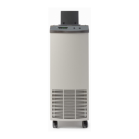
Moving or Uncrating the Bath
The bath is equipped with casters and should be rolled. It is not equipped with handles
and is not designed to be lifted.
When uncrating the bath, remove all of the accessories from the packing foam around the
bath. Remove the pre-formed foam. Gently ease the bath from the crate using the casters
to roll the bath. If it is required to lift the bath slightly to release it from the crate, two
people should carefully slide their hands under the bath and gently lift the bath only
enough to clear the packing foam and roll the bath from the crate. The area containing the
compressor will be heavier than the rest of the bath.
If it is required to move the bath after installation, empty the bath of fluid. DO NOT
move a bath filled with fluid. Unlock the casters and roll the bath. Do not attempt to
carry the bath. It is tall and heavy and is not provided with handles. Personal injury or
damage to the bath may occur.
Bath Environment
The Model 7341 Bath is a precision instrument, which should be located in an
appropriate environment. The location should be free of drafts, extreme temperatures and
temperature changes, dirt, etc. The surface where the bath is placed must be level.
Provide at least 6 inches (15 cm) of clearance around the instrument to allow sufficient
air circulation.
The top surface of the bath may become hot at high temperatures. Beware of the danger
of accidental fluid spills.
A fume hood or other adequate ventilation system should be used to remove any vapors
given off by hot bath fluid. Silicone oils require additional ventilation to prevent an oily,
dirty environment.
Tipping Prevention Bracket Installation
In order to create the safest possible conditions under use, your bath comes equipped with
a tipping prevention bracket. The installation of the bracket is required for compliance
with the international safety standard IEC 1010-1 (see Stability in Chapter 7) that applies
to the stability of the bath under normal operating conditions.
Installation On A Wood Floor
The wood floor installation kit includes lag bolts. Drill three 1/8 inch x 1 inch deep
(approximately 3 mm x 25.5 mm) pilot holes using the tipping bracket to mark the hole
placement. Use the lag bolts to install the bracket to the floor. Ensure that the bracket is
installed in such a way that the bath will have a minimum 6 inches of clearance for air
circulation. (See Figure 5-1). Screw the bracket securely to the floor.