7341
Users Guide
5-4
F
r
o
n
t
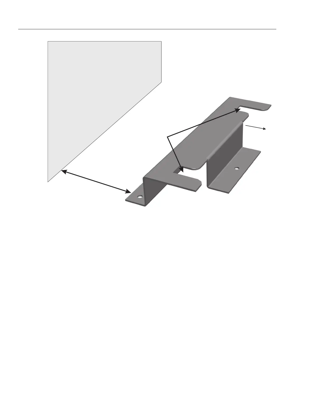
Caster Slots
8
.
5
"
(
2
1
.
6
c
m
)
Wall
haz002.eps
Figure 5-1. Tipping Prevention Bracket Installation
Installation On a Concrete Floor
Using a concrete drill and concrete drill bit, drill three ¼ inch x 1 ¼ inch deep
(approximately 6.5 mm x 32 mm) holes in the concrete floor using the bracket to mark
the hole placement. Drop the flare anchor bolt into the hole. Tightening the screw
expands the anchor in the drilled hole and secures the tipping bracket. Ensure that the
bracket is installed in such a way that the bath will have a minimum of 6 inches of
clearance for air circulation. (See Figure 5-1). Screw the bracket securely to the floor.
Installation Of The Bath
Slide the back casters of the bath completely into the tipping bracket. Lock the front
casters of the bath. Check that the bath is securely locked into the tipping bracket by
gently pushing on the bath. Proceed to fill the bath with the applicable bath fluid after
reading the entire Users Guide.
If you have any questions concerning installation of the tipping prevention bracket,
please contact a Fluke Authorized Service Center.
“
Dry-out” Period
If this equipment is used in a manner not specified by the manufacturer, the protection
provided by the equipment may be impaired.
Before initial use, or after transport, or after storage in humid or semi-humid
environments, or anytime the bath has not been energized for more than 10 days, the
instrument needs to be energized for a "dry-out" period of 2 hours before it can be
assumed to meet all of the safety requirements of the IEC 1010-1. If the product is wet or
has been in a wet environment, take necessary measures to remove moisture prior to