25
Parts and Controls
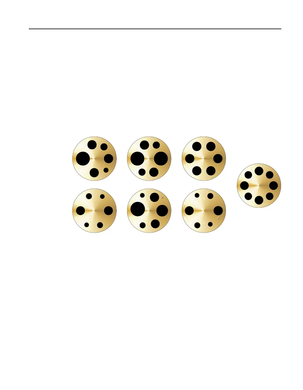
Accessories
●
9172-INSZ, Insert, Blank, 9172
●
9173-INSA, Insert, A, 9173, miscellaneous holes
●
9173-INSB, Insert, B, 9173, comparison holes
●
9173-INSC, Insert, C, 9173, four 0.25 inch holes
●
9173-INSD, Insert, D, 9173, metric miscellaneous holes
●
9173-INSE, Insert, E, 9173, metric, 0.25 inch reference, miscellaneous holes
●
9173-INSF, Insert, F, 9173, metric, 0.25 inch reference, comparison holes
●
9173-INSG, Insert, G, 9173, EA testing
●
9173-INSY, Insert, Custom, 9173
●
9173-INSZ, Insert, Blank, 9173
Figure 4
1/4
1/4
3/8
3/8
3/16
3/16
1/4
1/4
3/16
3/8
1/4
1/8
.25"
6
8
10
.25"
6
3
3
Insert “A” Insert “B” Insert “C”
Insert “D” Insert “E” Insert “F”
4
3
3
66
4
4
4
4
3
1/4
1/4
1/4
1/41/4
1/4
.228"
.228"
.228"
.228"
.199" .199"
.199" .199"
Insert “G”
Metrology Well insert options. Probe sizes indicated in inches for A, B, and C, and mil-
limeters for sleeves D, E, and F except for 0.25 inch reference holes in E and F.
 Loading...


