Getting Acquainted
7
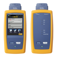
Physical Features
A Button for activating the visual fault locator (B) and output port (D). See
“Using the Visual Fault Locator” on page 37 and “Autotest in Far End Source
Mode” on page 32.
B Universal fiber connector (with dust cap) for the visual fault locator output.
The connector accepts 2.5 mm ferrules. The LED below the connector
indicates the locator’s mode (continuous or blinking).
C Input connector with dust cap. Receives optical signals for loss, length, and
power measurements. You can change the connector adapter to match the
connectors on the fiber under test. See Figure 3.
D SC output connector with dust cap. Transmits optical signals for loss and
length measurements.
The LED below the connector is red when the output is transmitting the
module’s shorter wavelength, and green for the longer wavelength.
amd64f.eps
W
*
Warning
Never look directly into optical
output connectors (B and D).
Some sources produce
invisible radiation that can
permanently damage your
eyes.
E Laser safety label (shown at right).
CAUTION
amd128i.eps
Figure 2. Fiber Module Features

 Loading...