14
3R, 3G, 5R, 5G
Users Manual
.
A
B
21
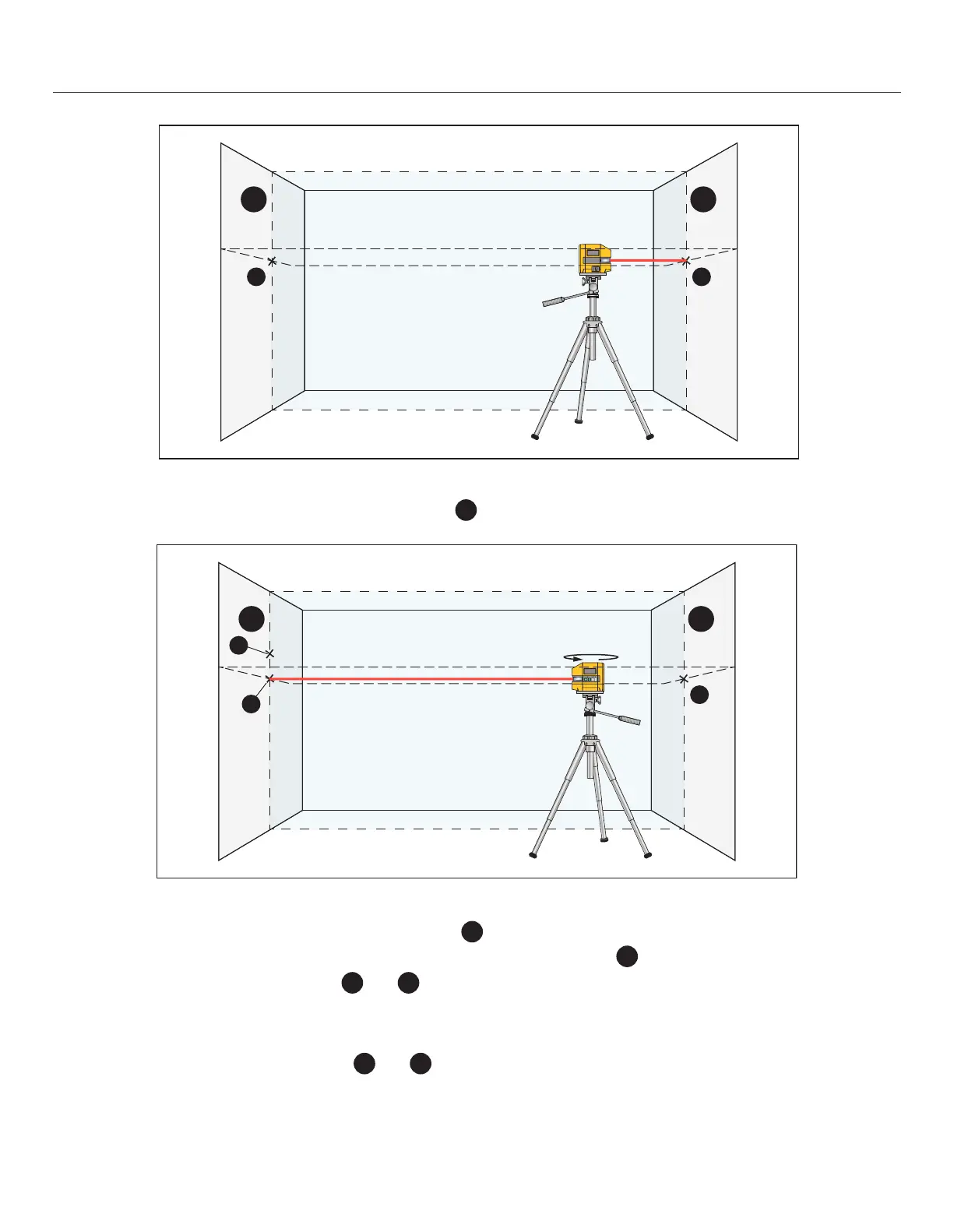
5. Align the height of the tool (using a tripod or by underlaying, if required) in such a manner that the front point of the
laser is projected against the previously marked point
2
on the wall B.
A
d
B
180°
2
3
1
6. Without changing the height, turn around the tool by 180°. Direct it against the wall A in such a manner that the vertical
laser line runs through sketched vertical line with point
1
.
Allow the tool to level in and mark the cross point of the laser on wall A (point
3
).
7. The dierence of both marked points
1
and
3
on wall A results in the actual height deviation of the tool alongside
the lateral axis.
On the measuring distance of 2 x 15ft = 30ft, the maximum allowable deviation is: 30ft x ±0.00394in/ft = +/- 1/8” (3
mm)
Thus the dierence “d” between points
1
and
3
must not exceed 1/8 in (max.).