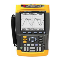
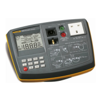
Fluke 190-062, -102, -104, -202, -204,-502, -504
Service Manual
Open the Test Tool, Remove the Battery Pack
3URFHHGDVIROORZV
7XUQWKHSODVWLFEDWWHU\GRRUVFUHZVRQHTXDUWHUWXUQFRXQWHUFORFNZLVHZLWKD
VWDQGDUGEODGHVFUHZGULYHU
5HPRYHWKHEDWWHU\DFFHVVGRRU
5HPRYHWKHEDWWHU\IURPWKHLQVWUXPHQW
Note
Do not short circuit the battery contacts. Do not open or damage the battery
housing.
,IDWWDFKHGUHPRYHWKHKDQJVWUDSDQGWKHVLGHVWUDSVHHWKHRemoving the Tilt
S
tand, Hang Strap, and Side StrapVHFWLRQ
/RRVHQWKHWZREODFNVHOIWDSSLQJVFUHZVWKDWIDVWHQWKHJUH\\HOORZLQSXWFRYHU
DURXQGWKH%1&LQSXWDQGEDQDQDVRFNHWV
5HPRYHWKHFRYHU
Note
When reinstalling the input cover do not forget to reinstall the flexible
sealing strip around the input sockets. The holes in this strip have a flat
side that must align with the flat side of the BNC input sockets. The strip
has six holes.
When reinstalling the input cover, reinstall the four steel pins (2x17 mm) in
the left side and right side of the Test Tool. The pins are used to attach the
hang strap and the side strap.
5HPRYHWKHWZRVFUHZV0[WRWDOOHQJWKIURPWKHERWWRPKROVWHU7KHVFUHZVILW
LQWRVTXDUHQXWVWKDWILWLQWRWKHUHDUFDVH
5HPRYHWKHERWWRPKROVWHU
Note
When reinstalling the holster, reinstall the two steel pins (2x17 mm) in the
left side and right side of the instrument. The pins are used to attach the
side strap. Take care that the yellow covers for the DC input and USB
inputs are in place correctly.
5HPRYHWKHIRXUVHOIWDSSLQJVFUHZVPPORQJWRWDOOHQJWKWKDWDWWDFKWKHUHDU
FDVH7ZRRIWKHVHVFUHZVDUHORFDWHGLQWKHEDWWHU\FRPSDUWPHQW
5HPRYHWKHUHDUFDVH
Note
When reinstalling the rear case, do not forget to put the steel plate
16x17 mm in place again. This plate is in the cavity on the right-hand side
of the Test Tool and can be used to attach a Kensington Lock.
When reinstalling the bottom case, take care that the flat cables to the LCD
and keyboard are not damaged between the case parts.

 Loading...


