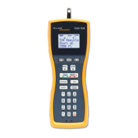
Display
LEDs
(All Models)
Description
y
x
w
v
u
t
s
Voltage level is backlit
z
Voltage level is more than ELV
limit (>50 V ac or >120 V dc)
a
Voltage is ac / phase in Single
Pole Phase test
d
DC
e
Voltage is positive or negative at
the indicator probe
b
Battery is low / Replace battery
M
Silent mode (T110)
f
Continuity or diode in forward
operation
g
Switchable load is ON (two buttons
pressed and current ows)
q r
3-phase sequence indication
detected left or right turning
phases with nonindicator probe
(L1) to indicator probe (L2)
1
2
4
3
5
6
7
gpn06.eps
LCD
(T130/T150)
Description
Silent mode (T130/T150)
Display is in HOLD mode
Voltage measurement (T130/T150)
or resistance measurement (T150)
Resistance measurement (T150)
AC Voltage measurement
DC Voltage measurement
Battery is low / Replace battery
How to Hold the Tester
Always hold the product behind the barrier to keep the
display in view. See Figure 4.
Warning
To prevent possible electric shock, never
touch the metal pins of the probes when
power is applied.
Self‑Test
The Tester has a built-in self test function.
Before and after use, do a self-test:
1. Touch and hold the probe tips together.
f shows and you can hear the beeper (when
active on the T110/T130/T150). Or, in the
silent mode, the LED is on (when active on the
T110). This makes sure that the test leads have
continuity.
2. Make sure that:
• batteries are good
• b (T90, T110) is NOT on
• B (T130, T150) does not show in the
display
3. Continue to hold the probe tips together for more
than three seconds.
4. Open the probe tips again. All LEDs (all but z and
g) must be on and all symbols in the LCD (T130,
T150) show for one second. This test makes sure
that all other internal circuits and indicators are
good.
5. Measure a known voltage such as a 230 V socket
outlet. This completes the self-test and includes
the >ELV circuit.
If the Tester fails the self-test or voltage test, do not
use. See To Contact Fluke for service.
For an inspection of the insulation, cables, and case,
see Safety Information.
www.calcert.com sales@calcert.com1.800.544.2843
0
5
10
15
20
25
30