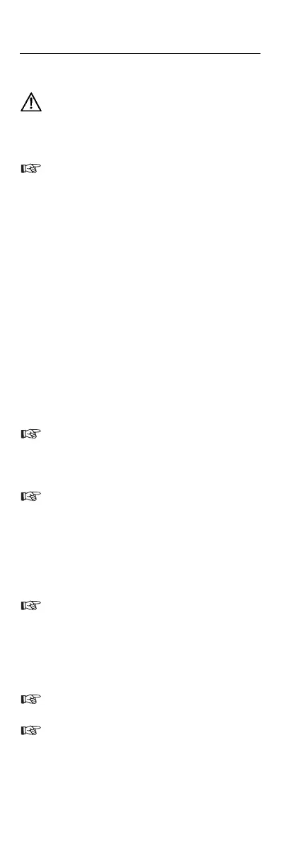
Voltage Test
Safety measures have to be met
• Connect both test probes with UUT.
From a voltage of > 12V the voltage
tester switches on automatically.
• The voltage is indicated by LED (3)
• For AC voltages the ”+” and ”-” LEDs are
illuminated and an additional signal
sound is audible.
• For DC voltages the LED (6) is illumina-
ted or a sound is audible.
• The instruments are equipped with an
LED row comprising: 12V, 24V, 50V,
120V, 230V, 400V, 690V.
• For DC voltage, the polarity of the volta-
ge displayed refers to the instrument test
probe (+).
Single-Pole Phase Test
The single-pole phase test starts at an
AC voltage of approx. 100V (pole >
100V AC).
When using single-pole phase tests to
determine external conductors, the
display function may be impaired
under certain conditions (e.g. for insu-
lating body protective equipment on
insulation locations).
The single-pole phase testing is not
appropriate to determine whether a
line is live or not. For this purpose, the
double-pole voltage test is always re-
quired.
A signal sound indicates the phase.
The LED (4) is illuminated in the dis-
play.
Fluke T50
Users Manual
9