T+/T+PRO English Instruction Sheet
Page 13
• It is not possible to switch the beeper off during a GFCI
test.
XWWarning
To avoid possible electric shock or personal injury,
follow these guidelines:
• When testing GFCIs installed in 2-wire systems,
(systems where no ground wire is available at
the receptacle) the Tester may give a false
indication that the GFCI is not functioning
properly. If this occurs, recheck the operation of
the GFCI using the test and reset button.
• The GFCI button test function should
demonstrate proper operations. However, if there
is cause to verify proper operation of the GFCI
receptacle in a 2-wire system, apply one test
probe of the Tester to the energized input of the
GFCI receptacle while applying the alternates
test probe to a known external neutral or ground
reference location external to the GFCI
receptacle. Operate the GFCI button on the
Tester as described in the Instruction Sheet to
verify the GFCI receptacle is operating properly.
Rotary Field Direction (T+ PRO Only)
This test shows the direction of a rotary field in a three-phase
system when measured phase to phase. The LCD indicates phase
rotation for a right or left-hand turning field from one phase to the
next in a three-phase system.
Note
If measuring from phase to neutral at a panel or single-
phase outlet, the Tester may indicate Jor K.
However, this is not a valid reading. A valid reading can
only come from a phase to phase circuit. The rotary field
function is specified for use on line (mains) systems only.
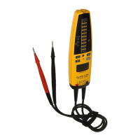
To perform a rotary field direction test, see Figure 5:
1. Attach one probe to the center probe holder on the back of
the Tester and grip the main body with one hand.
2. Attach both probes to the test points. If the red lead is 120
degrees ahead of the black lead, K is displayed. If the red
lead lags the black lead by 120 degrees, J is displayed. In
both situations the voltage is shown on the display. If a phase
rotation measurement is not possible, no arrows will light but
the voltage appears on the display.
1.800.868.7495info@Fluke-Direct.ca
Fluke-Direct.ca