After you have connected the motor cable to the pump, connect the motor cable and the
control cable to the starter equipment.
WARNING:
Do not install the starter equipment in an explosive zone or in the sump.
Three thermal contacts are incorporated in the stator. They are normally closed.
Thermal contacts must never be exposed to voltages higher than 250 V, breaking current
maximum 6 A at a power factor 0.6. It is recommended that the thermal contacts are
connected to 24 V over a separate fuse to protect any other automatic equipment.
Cable charts
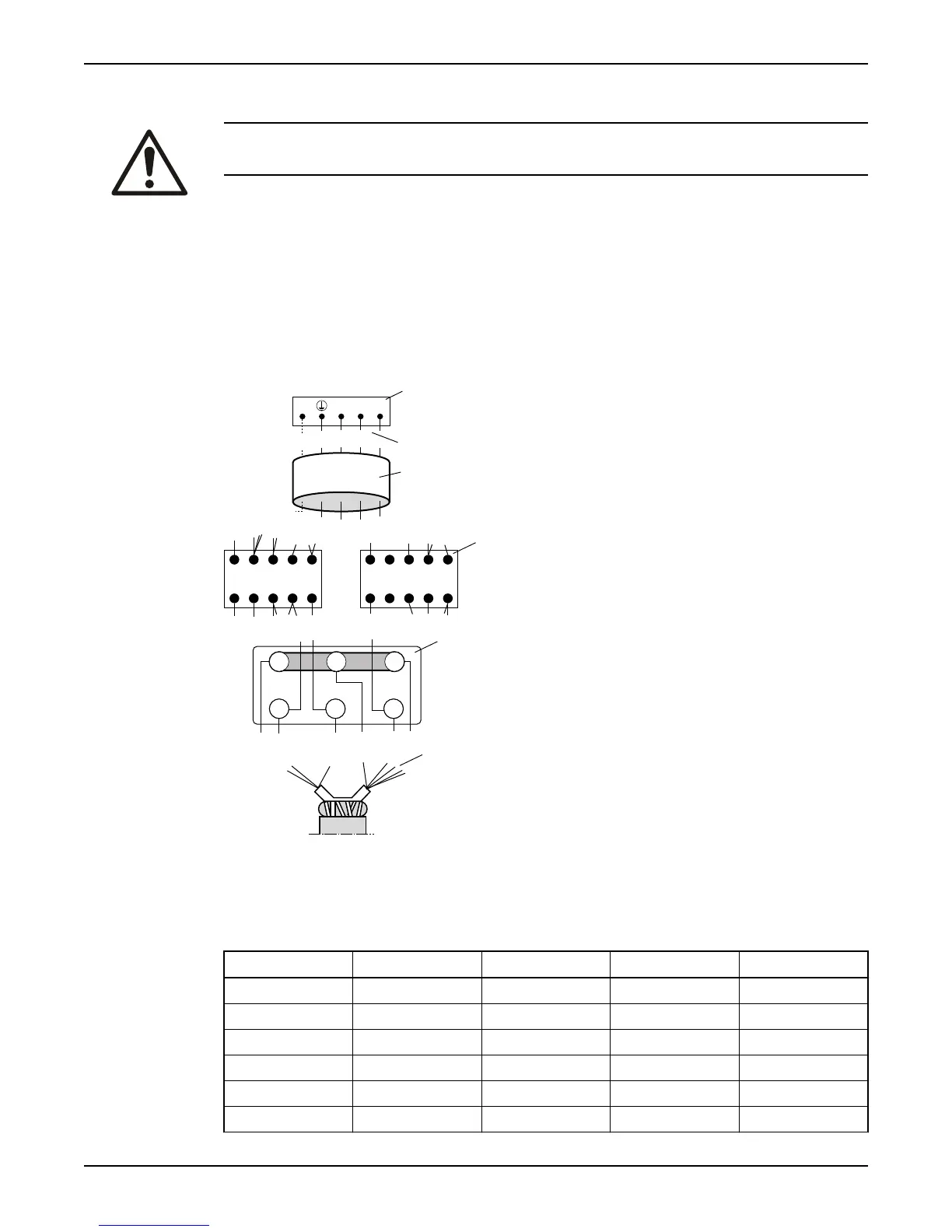
Connection locations
U2W2 V2
V1U1 W1
1 3 5 13 A2
2 4 6 14 A1
A2 44 32 22 14
A1 43 31 21 13
L1GC L2 L3
1
2
4
3
5
6
1. Starter equipment
2.
Mains and control leads
3. Motor cable (or cables)
4. Contactor unit on the pump (if any)
5. Terminal board on the pump (if any)
6. Stator leads
Colors and marking of the mains leads
Mains SUBCAB 7GX SUBCAB 4GX SUBCAB AWG SUBCAB Screened
L1 Black 1 Brown Red Brown
L2 Black 2 Black Black Black
L3 Black 3 Grey White Grey
L1 Black 4 - - -
L2 Black 5 - - -
L3 Black 6 - - -
Installation
20 2125 Installation, Operation, and Maintenance Manual