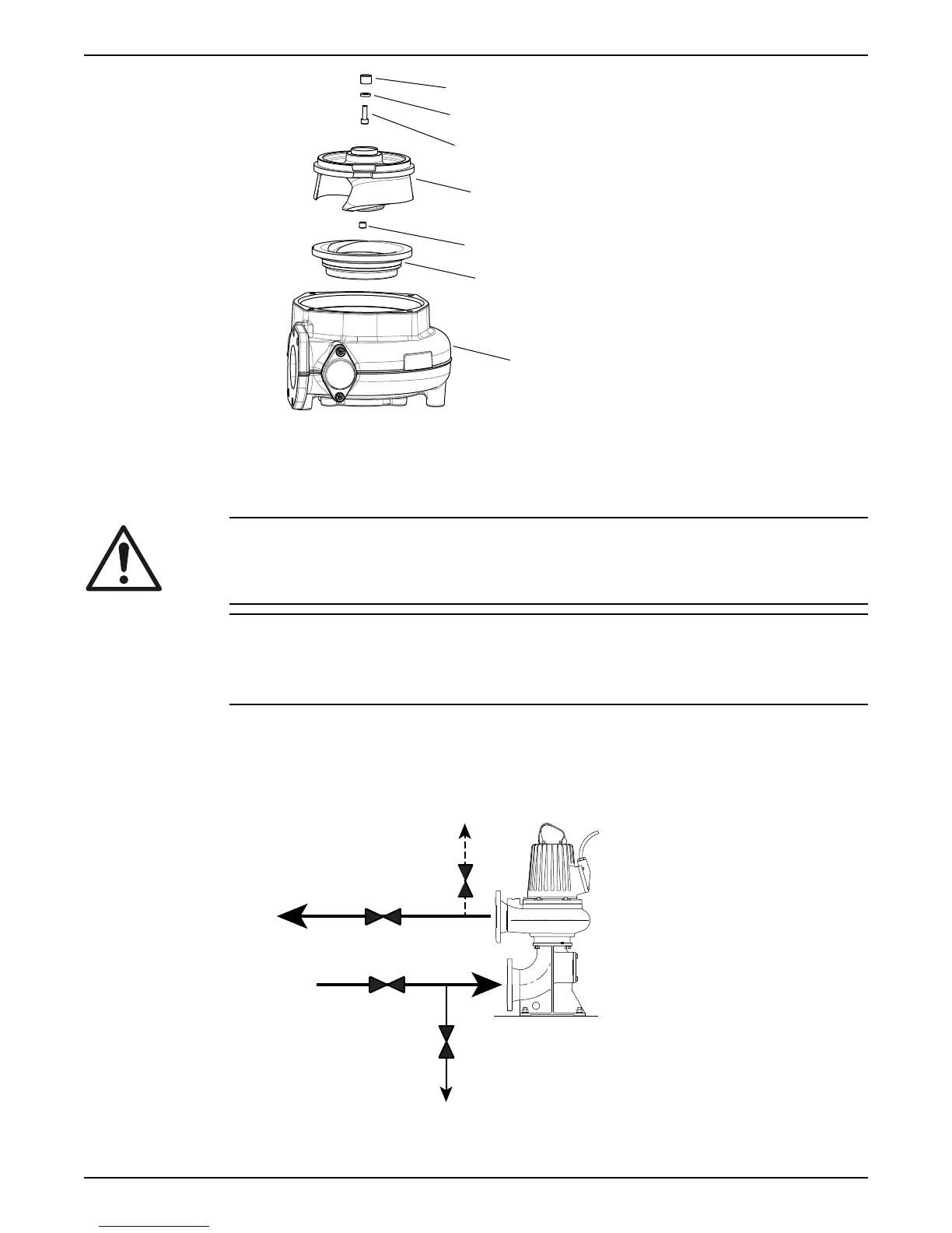
1. Conical sleeve
2. Washer
3. Impeller screw
4. Impeller
5. Plug
6. Insert ring
7. Pump housing
CAUTION: Cutting Hazard
Worn parts can have sharp edges. Wear protective clothing.
NOTICE:
When laying the pump on its side, do not allow the weight of the pump to rest on any
portion of the impeller. The impeller must not be allowed to make contact with the
concrete floor or other hard and rough surfaces.
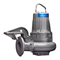
6.4.4.1 Prepare the pump for removal: T-, Z-installations
The pump must be removed from the installation to change the impeller.
1. Close valves A and B on the inlet and outlet lines.
See the following figures.
6 Maintenance
58 Flygt 3085 Installation, Operation, and Maintenance Manual