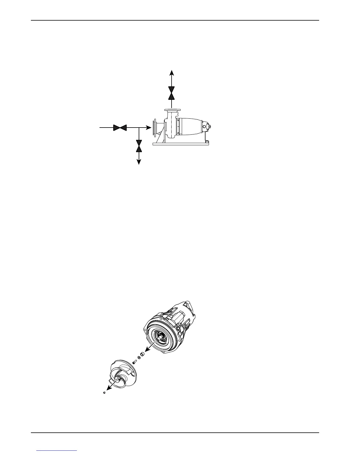
1. Outlet line
2. Inlet line
3. Line to drain
4. Air vent
Figure 19: Valves A-D for T-installation (generic pump shown)
1. Outlet line
2. Inlet line
3. Line to drain
Figure 20: Valves A-C for Z-installation (generic pump shown)
2. Drain the pump by opening valve C on the drain line.
3. Remove the pump from the installation.
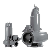
6.4.4.2 Remove the Adaptive-N impeller: P, S, T, Z installations
To see which pumps are Adaptive-N, see Product Description (page 10).
1. Remove the pump housing.
2. Remove the impeller.
a) Remove the plug.
b) Loosen the impeller screw.
c) Remove the impeller.
Use the impeller puller or the crowbars.
d) Remove the impeller screw, the washer, and the conical sleeve.
6.4.4.3 Install the Adaptive-N impeller: P, S, T, Z installations
To see which pumps are Adaptive-N, see Product Description (page 10).
6 Maintenance
Flygt 3085 Installation, Operation, and Maintenance Manual 59