INSTALLATION
The installation shall be performed by an authorised electrician according to local safety
regulations.
WARNING:
Before installing, make sure that no voltage is applied to the equipment.
Check that the rated voltage of FPC100 corresponds with the supplying line voltage. The
rated voltage can be found on the rating plate on the side of the control unit.
FPC 100 is mounted on a standard DIN-rail, 35 mm. Dimensions, temperature range and
other necessary data for the installation can be found in
TECHNICAL SPECIFICATIONS
(page 22).
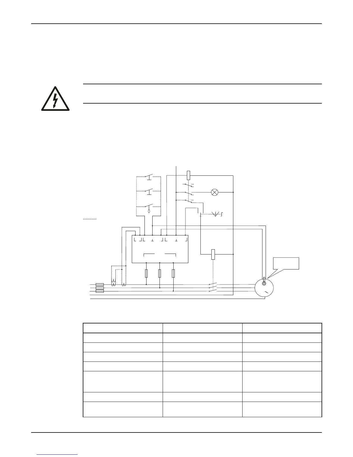
PE
L1
L2
L3
N
M
3
Max
240VAC
Hand
I
Dig
in
Temp Alarm Pump
1 3
4
5 7
8
6
9
L1
11
L2
L3
13
2
Supply
Auto 0
Alarm
Auto-set
Reset
High level
Thermistor (PTC)
or
Thermal contact
Alternative connection
K
FPC100
R
Connection terminals
No Label Function
1 I Current transformer input
2 I Current transformer input
3 DIG IN Digital input for closing contact
4 DIG IN/TEMP Signal ground for terminals 3 and 5
5 TEMP Input for thermistor (PTC), thermal
contact and/or any voltage-free
opening contact
6 ALARM Alarm relay output
7 ALARM/PUMP Common input for alarm- and pump
relay
INSTALLATION
Single pump controller Installation and user manual for FPC100 5