Page 14 • MN01029 Issue/Rev. 0.5 (6/11)
Section 2 – Clearance Checks (continued)
Blade End to Rotor
This check can be made with the rotor assembly in the
meter housing or situated on a flat, even surface.
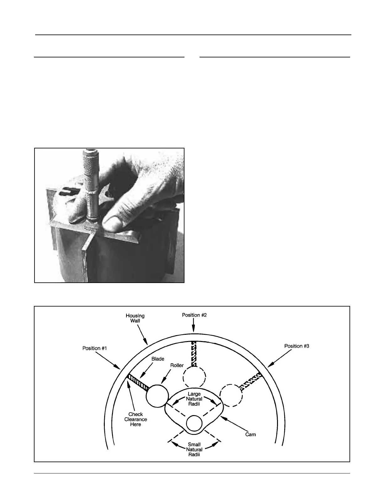
1. Place depth micrometer on the rotor over the blade
end as shown in Figure 51 and check findings against
Clearance Guide on Page 12.
•Ifadepthmicrometerisnotavailable,afeelergauge
with a straight-edged block of metal may be used.
2. If blade extends over rotor, drop top end to meet
clearance requirement.
3. If blade exceeds clearance requirement, replace.
Blade Roller Over Radius Portion of Cam
1. Rotate rotor until a blade is in Position No. 1 as shown
in Figure 52.
2. Forcing blade against housing wall, check clearance
between blade tip and housing wall from top to bot-
tom. Note clearance.
3. Forcing blade away from wall, again check clearance.
• The difference between these two clearance
readings is the blade roller over radius portion
of cam clearance in this position. Check against
Clearance Guide Table 2, Page 12.
4. Rotate rotor assembly until this same blade is in the
middle of the measuring chamber (Position No. 2),
Figure 45.
5. Repeat Steps 2 and 3 and check findings against
Clearance Guide Table 2, Page 12.
6. Again rotate rotor until blade is in Position No. 3,
Figure 45, and repeat Steps 2 and 3. Check clear-
ances against Clearance Guide, Table 2, Page 12.
7. Repeat Steps 1 through 6 with other blade assembly.
8. Record findings, if satisfactory, in Meter Clearance
Record, Page 19.
9. If clearances on any portion of radius of cam do not
fall within recommended limits as shown in Clearance
GuideTable2,Page12,thencheckthefollowing:
• If tolerances are in excess of recommended
clearances, determine if cam or blade roller is worn
(normally, the cam will have the most wear). Replace
worn parts and recheck clearances.
•Therollerinanintegralpartofthebladeassembly
in T-11 and I-75 Meters. In this case, the entire blade
assembly would have to be replaced.
Figure 51
Figure 52