Issue/Rev. 0.5 (6/11)
MN01029 • Page 9
Section 1 – General Information and Description (continued)
Figure 30
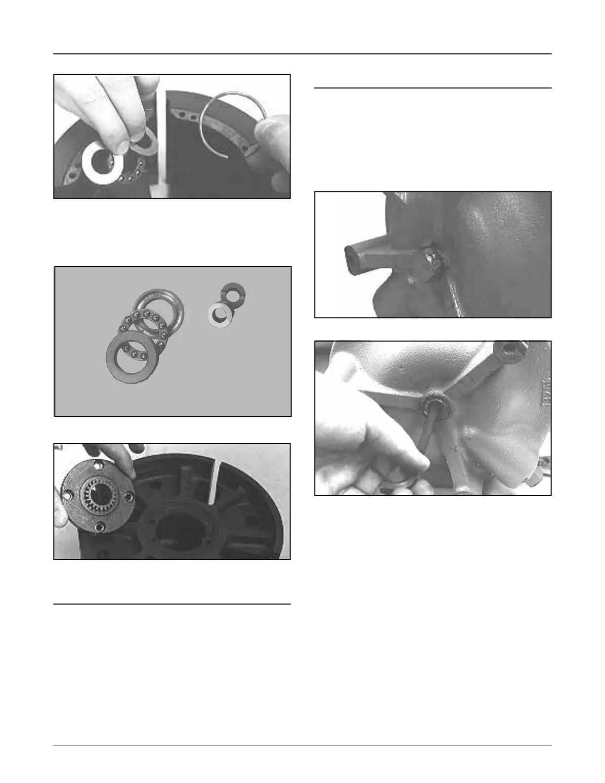
11. Remove thrust bearing and snap ring, Figure 30.
•Seealternatebearings,Figure31.
12. Turn the rotor over and remove gear plate, Figure 32.
Adjusting Rotor End Clearances
Caution: Before any adjustments can be made, the
meter must be removed from the line or drained.
T-11 or I-75 Meters Only
The T-11 or I-75 Meter can have the rotor and adjust-
ments made without removing the calibrator on top of
the meter. An access hole is available on the bottom of
the meter for this adjustment, Figure 33.
Figure 33
Reassembly of Meters
Reassembly is essentially the reverse of the disas-
sembly procedure. Be sure to observe the reassembly
precautions noted duringteardownofunit.
To assist in the reassembly of the meter, refer to the
appropriate parts lists (see Related Publications).
Upon reassembling the meter, clearance checks are
mandatory. Refer to Section 2 — Clearance Checks,
Page 12.
Figure 32
Figure 31
Tungsten Carbide
Thrust Bearing
(SC13 Meter)
Standard
Thrust Bearing
For purposes of illustration, the meter has been placed
on its side for this series of pictures. However, when
actually performing this adjustment, the meter must be
in a vertical position.
1.Withaccessplugremoved,rotaterotorthrougheither
housing port and turn adjusting screw (using a 1/4"
Allen wrench) counterclockwise until resistance is
felt in the rotor rotation, Figure 34.
•Ifrotorisalreadyhardtoturn,thenturnadjusting
screw clockwise until rotor just begins to rotate.
2. Rotor is now in the full top position. Mark this position
on the hub of the meter (Point A), Figure 34.
• Also mark Allen wrench for reference (Point B),
Figure 34.
Figure 34