Page 12 • MN01029 Issue/Rev. 0.5 (6/11)
Meter Rotor RotorAdj.Total BladeEnd BladeRollerOverNatural BladeTip
ModelNo. toBlock EndClearance BladeSlot toRotor RadiusPortionofCam TowardHousing
(1) (2) (3) (4) (5)
T-11 or I-75 .002 - .004 .004 - .008 .0015 - .0040 .000 - .003 .001 - .005 .001 - .003
T-20 or I-150 .002 - .004 .005 - .009 .0015 - .0035 .000 - .003 .001 - .005 .0035 - .0055
T-40 .002 - .004 .006 - .010 .0015 - .0035 .000 - .005 .001 - .005 .0035 - .0050
SC-13 .002 - .004 .005 - .009 .001 - .004 .000 - .003 .001 - .005 .003 - .005
SD3-S1 or SD-30 .002 - .004 .006 - .010 .0015 - .0035 .000 - .005 .001 - .005 .0035 - .0050
SF4 .003 - .006 .005 - .011 .0015 - .0045 .000 - .004 .001 - .005 .004 - .006
SG6 .003 - .006 .007 - .013 .0015 - .0055 .000 - .004 .001 - .005 .006 - .008
SD-NF .002 - .004 .006 - .010 .0015 - .0035 .000 - .005 .001 - .005 .0035 - .0050
T40-NF .002 - .004 .006 - .010 .0015 - .0035 .000 - .005 .001 - .005 .0035 - .0055
Section 2 – Clearance Checks
Table 2 – Clearance Guide
Note: Standard clearances for temperatures less than 150°F and/or viscosities less than 400cP.
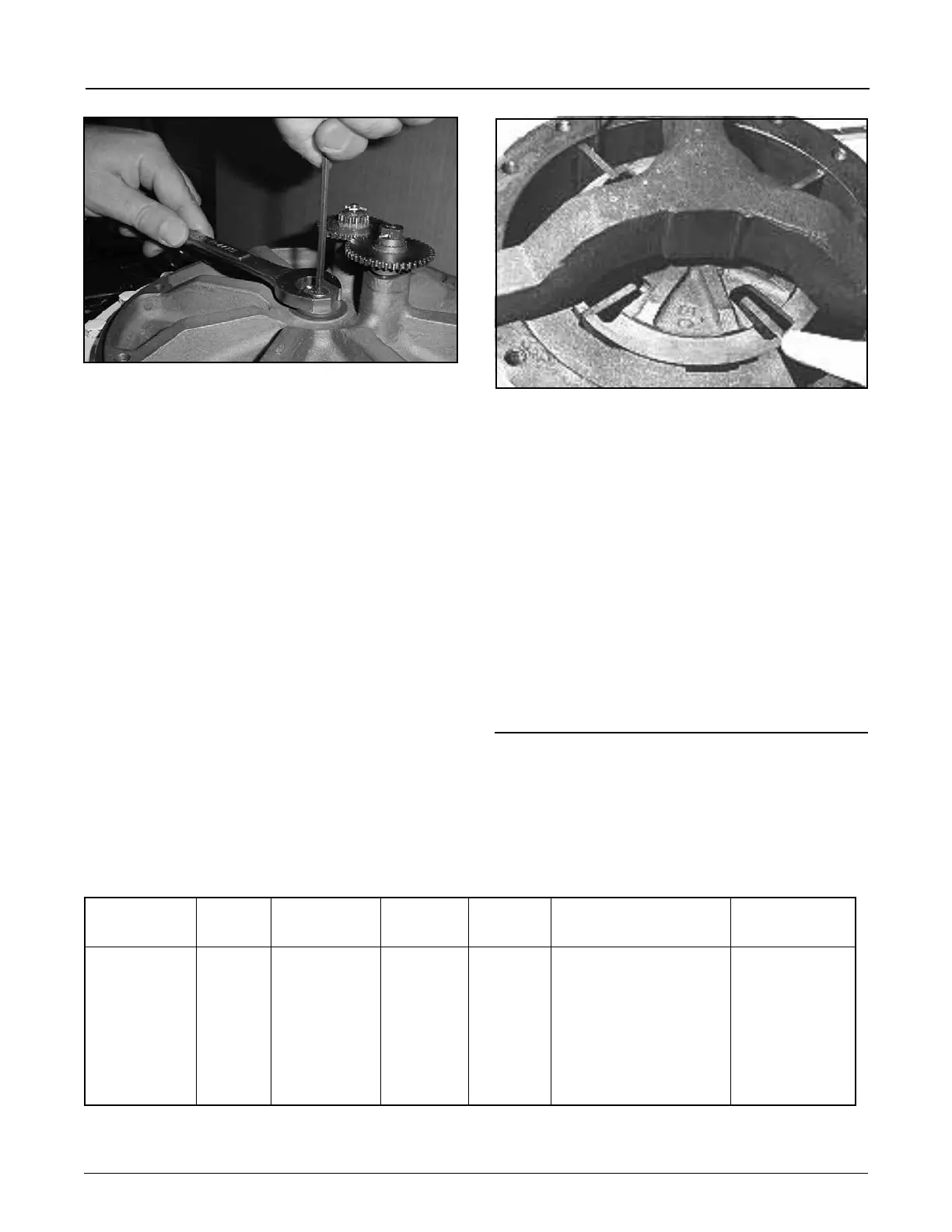
7. Install the screw. Hold the Adjusting Cap with a ¾”
wrench while tightening the screw with a 5/32" Allen
Head wrench (Figure 46). Take precaution not to
move the Adjusting Cap when tightening the screw.
The screw must be tight. After tightening the screw
spin the Jack Shaft gear to check the free movement
of the rotor. If the rotor does not move free the adjust-
ment will need to be redone.
The rotor end adjustment is now complete. The Meter
Adaptor can now be installed and the meter returned
to service.
Rotor should now rotate freely. If not, recheck all clear-
ances and repeat Steps 1 through 6.
8. Replace adjusting screw cap.
•ApplyMasterGasketbyLoctitesealantorequivalent
to top of cover to provide a good seal between cap
and cover.
• The adjusting screw cap has a hex indentation
on the underside which will slip over the adjust-
ingscrew.Whentighteningdownscrewincap,do
not allow the cap to rotate, as this will change the
adjustment.
The clearances listed in the Clearance Guide, Table 2,
are standard clearances (see note) and are to be used
Figure 47
Figure 46
only as a guide in determining whether or not a part
should be repaired or replaced. However, at no point
should a clearance exceed 50% of the listed maximum.
The ability of the meter to obtain acceptable repeatability
and linearity for the particular operating conditions, such
as flow rate, viscosity, lubricity, abrasive contaminants,
and intermittent or continuous duty, should be consid-
ered as a better guide rather than clearance alone.
The procedure for checking clearances on all meters
covered by this manual are identical. For this reason,
all illustrations are of the T-11 Meter.
In order to check the clearances in a meter, the rotor
assembly must first be placed in the bottomed position
using the following methods.
T-11 or I-75 Meter
Method No. 1:
Turn adjusting screw on bottom of housing clockwise
until rotor assembly meets friction and is hard to turn. At
this point, the meter is resting on the bottomshelf of the
housing. Then raise rotor just enough for it to be free of the
base by turning same adjusting screw counterclockwise.