Page 16 • MN01029 Issue/Rev. 0.5 (6/11)
Section 3 – Meter Repairs (continued)
Caution: Care should be taken not to remove too
much metal from the blade. Also, blades should
have sharp, square, clean-cut edges.
3. After all the blade ends have been dressed down,
reinstall rotor assembly back into the housing.
Recheck clearances.
• If not enough metal is removed the rst time,
the process must be repeated until the desired
clearances are obtained.
4. Record these measurements as “As Assembled”
clearances.
5. Adjust rotor end clearances after the meter is
completely assembled, as outlined on Page 12.
Blade Roller Replacement (T-20, I-150, SC,
SD, SF, and SG Meters)
Remove rotor assembly from housing and disassemble
as outlined on Page 2 or 6.
1.Withbladeassemblyremovedfromtherotor,remove
cotter pin and drive groove pin from blade assembly,
Figure 58.
2. Slip roller out of slot in blade and install new roller.
3. Reinstall groove pin and cotter pin.
4. Check companion roller on blade for wear or
damage. Replace if necessary.
5. Reinstall blade assembly into rotor and reassemble
meters, observing all clearance checks.
Figure 57
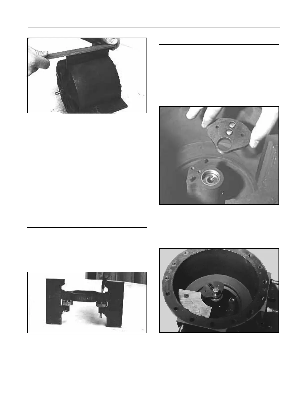
Cam Replacement (T-11 or I-75 Meters Only)
Disassemble meter following Steps 1 through 4 under
Disassembly of Model T-11 and I-75 Meters, Page 2 and
3,andproceedasfollows:
1.With rotor assembly removed, unscrew hold-down
screws and lift cam straight up from housing center
hub, Figure 59.
2. Replace locating pins as necessary. (Pins may remain
pressed into the cam. Be sure to press new pins into
the housing center hub.)
3. Place cam setting bushing (see Suggested Tools and
Fixtures, Page 2) in center hub.
4. Position new cam on center hub by placing it over top
of cam setting bushing as shown in Figure 60.
5. Tighten cam hold-down screws.
6. Place cam setting fixture (see suggested Tools and
Fixtures, Page 2) on bottom shelf, Figure 60, and slide
between cam face and measuring chamber wall.
Figure 58
Figure 52
Figure 60